Switch power supply circuit

A switching power supply circuit, switching circuit technology, applied in the direction of high-efficiency power electronic conversion, electrical components, climate sustainability, etc., can solve the problems of low reliability of switching power supply circuits, and achieve the effect of high reliability and not easy to burn out

Active Publication Date: 2011-05-11
INNOCOM TECH (SHENZHEN) CO LTD +1
View PDF4 Cites 9 Cited by
  • Summary
  • Abstract
  • Description
  • Claims
  • Application Information

AI Technical Summary

Problems solved by technology

[0006] In order to solve the problem of low reliability of the switching power supply circuit in the prior art, it is necessary to provide a switching power supply circuit with high reliability

Method used


Image

  • Switch power supply circuit
  • Switch power supply circuit
  • Switch power supply circuit

Examples


Embodiment Construction

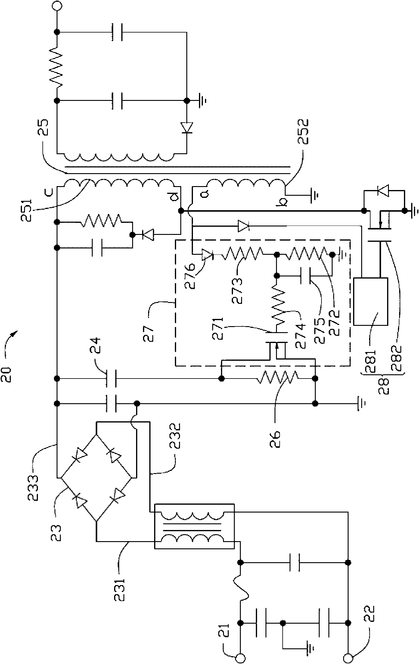
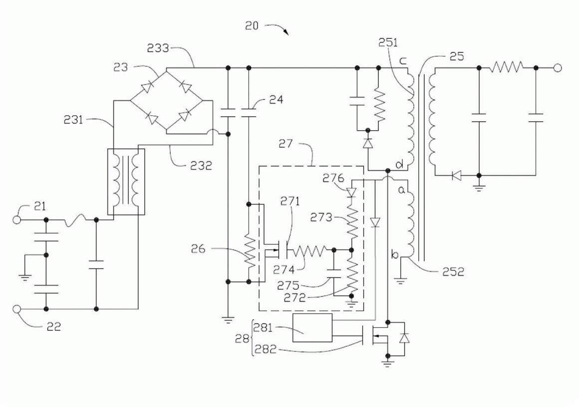
[0012] see figure 2 , is a schematic diagram of a preferred embodiment of the switching power supply circuit of the present invention. The switching power supply circuit 20 includes two input terminals 21, 22 for entering commercial power, a rectification filter circuit 23, a filter capacitor 24, a transformer 25, a first current limiting resistor 26 and a first switch circuit 27 and A second switch circuit 28 .

[0013] The rectification and filtering circuit 23 includes two AC voltage input terminals 231 , 232 and an output terminal 233 . The transformer 25 includes a primary winding 251 and an auxiliary winding 252 . The primary winding 251 receives the DC voltage output by the rectification and filtering circuit 23 . The primary winding 251 includes a terminal c and a terminal d, the terminal c is connected to the output terminal 233 of the rectification and filtering circuit 23 , and the terminal d is connected to the second switch circuit 28 . The auxiliary winding ...


PUM


Abstract

The invention relates to a switch power supply circuit which comprises a rectifier filter circuit, a filter capacitor and a transformer, wherein the rectifier filter circuit is used for receiving an external alternating voltage and providing a DC voltage to the rectifier filter circuit and a transformer after performing rectification and filtration on the external alternating voltage, the switch power supply circuit further comprises a first current-limiting resistor and a first switch circuit connected with the two ends of the first current-limiting resistor, one end of the filter capacitor is connected to the rectifier filter circuit, the other end of the filter capacitor is grounded through the first current-limiting resistor, and the first switch circuit is disconnected instantaneously when the filter capacitor starts to charge and is connected during the later charging process of the filter capacitor. In the invention, the filter capacitor of the switch power supply circuit has low possibility of being burnt out, and the reliability is higher.

Description

technical field [0001] The invention relates to a switching power supply circuit, especially a switching power supply circuit with high reliability. Background technique [0002] Switching power supply circuits have the characteristics of low loss, high conversion efficiency, small linear change, and stable operation, so they are widely used in LCD TVs, cathode ray tube TVs and other display devices and other consumer electronics products. [0003] see figure 1 , is a schematic diagram of a conventional switching power supply circuit. The switching power supply circuit 10 includes two input terminals 11 and 12 for connecting to commercial power, a rectification and filtering circuit 13, a common mode inductor 14, a fuse 15, a thermistor 16, a filter capacitor 17, a plurality of safety regulations Capacitors C1 , C2 , C3 and a transformer 18 . The common mode inductor 14 and the plurality of safety capacitors C1 , C2 , C3 are used to filter out the clutter of the AC signal...

Claims


Application Information

Patent Timeline
Patent Type & Authority Applications(China)
IPC IPC(8): H02M5/42H02M3/06
CPCH02M1/36H02M3/33507H02M1/0048Y02B70/10
Inventor 周和康林静忠
Owner INNOCOM TECH (SHENZHEN) CO LTD
Why Eureka
Try Eureka