Gasification with separate calcination

A technology of calcination and calciner, which is applied in ceramic production workshops, cement production, lighting and heating equipment, etc., and can solve problems such as low efficiency

Inactive Publication Date: 2011-05-11
F L SMIDTH & CO AS
View PDF3 Cites 1 Cited by
  • Summary
  • Abstract
  • Description
  • Claims
  • Application Information

AI Technical Summary

Problems solved by technology

Also, the available heat is at a low level, i.e., its efficiency in relation to power generation is relatively small, i.e., at a level around 15-20%

Method used


Image

  • Gasification with separate calcination
  • Gasification with separate calcination
  • Gasification with separate calcination

Examples


Embodiment Construction

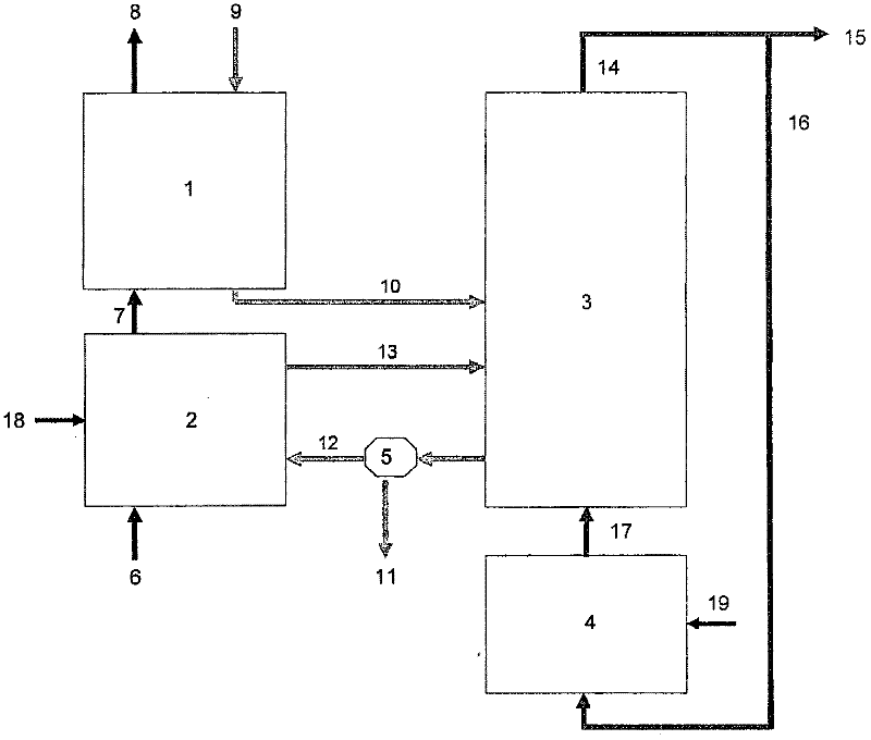
[0023] Depend on figure 1 It can be seen how the hot gas 7 is used to heat the raw cement meal 9 in the preheater 1 . The preheated cement raw meal 10 is introduced into the calciner 3, where the cement raw meal is calcined. A part 15 of the gas 14 from the calciner 3 is withdrawn, while a second part 16 is directed to the gasifier 4 , which is fed with fuel and, if relevant, oxygen 19 . Gas 17 from gasifier 4 is recycled to calciner 3 . Depend on figure 1It can also be seen how the calcined raw cement meal from the calciner 3 is directed to a splitter gate or similar device from which a portion 11 of the calcined raw cement meal is directed to a kiln (not shown) and otherwise A portion 12 is directed to the lift duct 2 . The riser duct 2 receives exhaust gas 6 from a kiln (not shown) as well as secondary fuel and, if relevant, air 19 . The calcined cement raw meal 13 is separated from the exhaust gas 6 by means of a cyclone or similar and recycled to the calciner 3 .

...


PUM


Abstract

A description is provided of a method and an apparatus for manufacturing of cement whereby cement raw meal is preheated in a preheater, calcined in a calciner by contact with hot gases which are introduced into the calciner via a gas inlet and being diverted from the calciner via a gas outlet, and where calcined cement raw meal is diverted from the calciner, burned into cement clinker in a kiln and subsequently cooled in a clinker cooler. The method and the apparatus are peculiar in that at least a portion of the calcined cement raw meal diverted from the calciner is heated further in a separate system to a temperature which exceeds the calcination temperature, and being subsequently recirculated to the calciner, and in that at least a portion of the gases which are diverted via the gas outlet of the calciner is removed from the plant with a view to storage in the underground or other additional treatment.

Description

field of invention [0001] The invention relates to a method of producing cement, wherein cement raw meal is preheated in a preheater and calcined in a calciner by contact with hot air which is introduced into the calciner via a gas inlet and From the calciner via a gas outlet, the calcined cement raw meal is drawn from the calciner, fired into cement clinker in a kiln, and subsequently cooled in a clinker cooler. The invention also relates to a device for carrying out the method. Background technique [0002] In modern cement production plants, raw materials are usually heated by heat exchange with exhaust gases from kilns and / or calciners. This takes place in a so-called suspension preheater, which is usually a column formed by a number of cyclones connected in series. Calcination is usually carried out in the pipe section at the bottom of the column, where the temperature and residence time are sufficient for calcination to occur, ie decomposition of the limestone, there...

Claims


Application Information

Patent Timeline
Patent Type & Authority Applications(China)
IPC IPC(8): F27B7/20C04B7/43C04B18/16C04B7/36
CPCC04B7/365C04B7/367C04B7/434C04B2290/20F27B7/2058Y02P40/121
Inventor 克劳斯·朱勒
Owner F L SMIDTH & CO AS
Why Eureka
Try Eureka