
Method and device for separating gas from liquid

A technology of gas-liquid separation and separator, which is applied in separation methods, combined devices, and separation of dispersed particles, etc. It can solve the problems of non-compliance with safety requirements and lack of steam, so as to save steam consumption and prevent landfill gas from being discharged. Effect

Active Publication Date: 2011-05-18
ACRE COKING & REFRACTORY ENG CONSULTING CORP DALIAN MCC +1
View PDF6 Cites 0 Cited by
  • Summary
  • Abstract
  • Description
  • Claims
  • Application Information

AI Technical Summary

Problems solved by technology

Because at present, most landfills in China, especially in the south, do not have steam available for the condensate steam injection lifter, and the use of compressed air injection lift does not meet the safety requirements

Method used


Image

  • Method and device for separating gas from liquid
  • Method and device for separating gas from liquid
  • Method and device for separating gas from liquid

Examples


Embodiment Construction

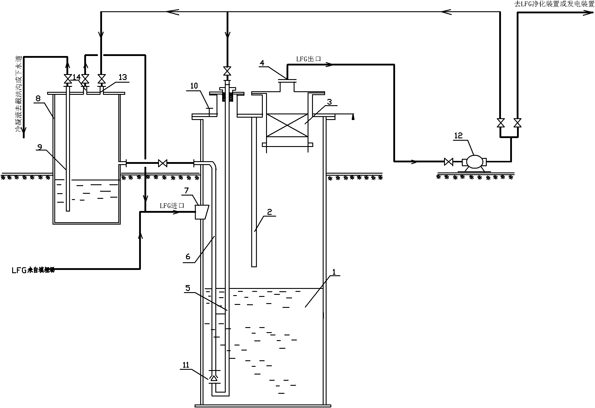
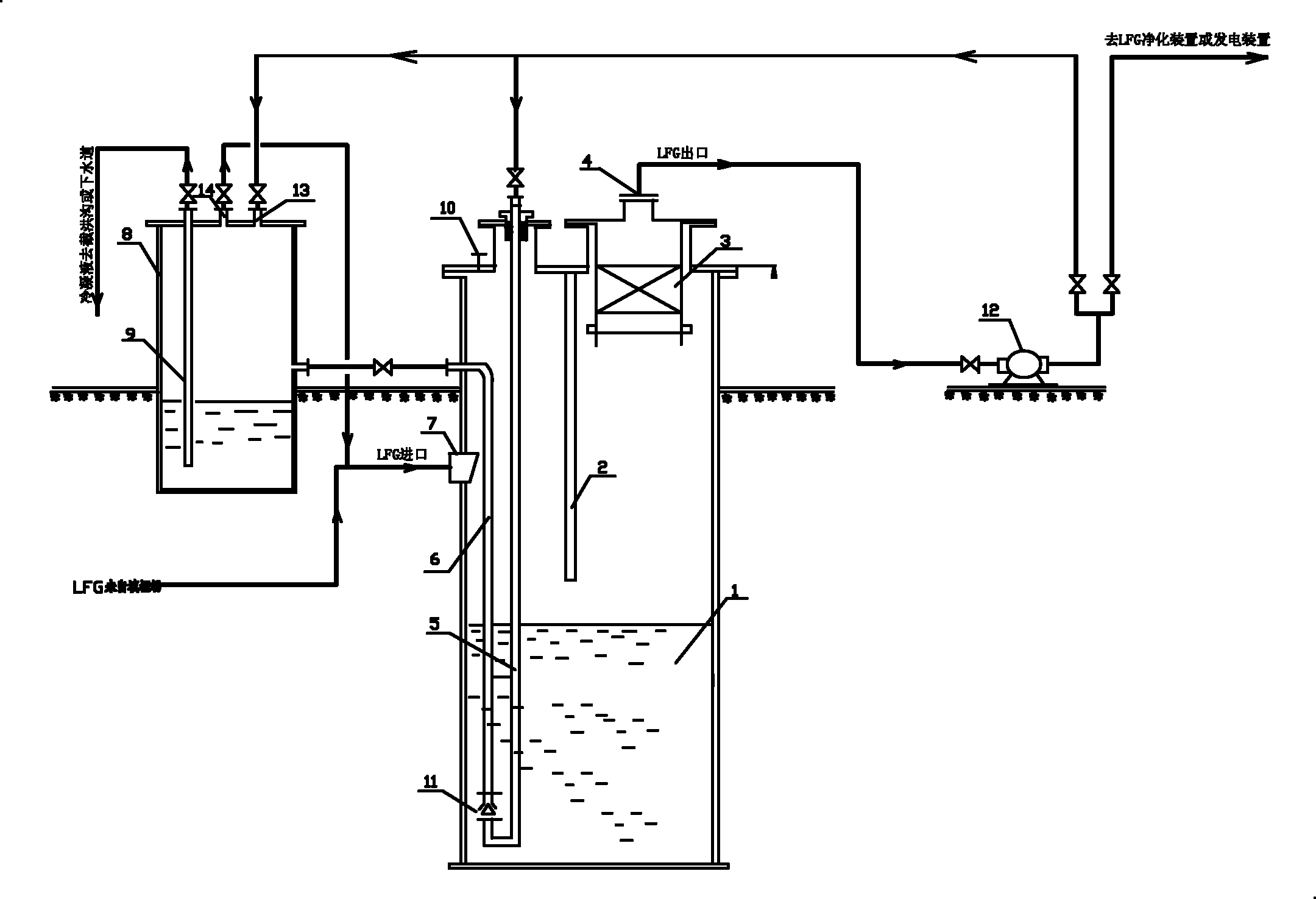
[0021] See figure 1 , a gas-liquid separation device, including a settling chamber 1, a baffle plate 2, a foam catcher 3, an LFG gas outlet pipe 4, an LFG gas inlet pipe 7, and a gas stripping medium separator 8, and the settling chamber 1 is provided with a condensate riser 6 and the baffle plate 2, the upper part is provided with a liquid level gauge interface 10, and the bottom of the condensate riser 6 is provided with a spray riser 11, and the condensate riser 6 is connected to the low-pressure landfill gas inlet pipe 5 output from the blower through the spray riser 11 Connection; the outlet at the top of the condensate riser 6 communicates with the gas stripping medium separator 8. The air-lifting medium separator 8 is provided with a low-pressure landfill gas inlet 13 output from the blower, and the air-lifting medium separator 8 is provided with a condensate discharge pipe 9, and the lower opening of the condensate discharge pipe 9 communicates with the condensate to ...


PUM


Abstract

The invention relates to a device for separating gas from liquid for refuse filling gas and other biogas. The invention is characterized in that low-pressure filling gas output by a blower is used as a working medium for jetting and lifting condensate liquid, and after the working medium is subjected to gas-liquid separation in a gas stripping medium separator, gas returns to a gas inlet of a settling chamber and is used as the filling gas of the working medium for completely recycling; after the low-pressure filling gas working medium is input into the settling chamber, the working medium can meet the requirement for one-time lifting height of the condensate liquid; and if the condensate liquid needs to be lifted once again, the low-pressure filling gas output by the blower is introduced into the gas stripping medium separator to pressurize the condensate liquid to realize secondary lifting. The method can be used for completely recovering the filling gas used as the working medium, thereby stopping the working medium from being directly exhausted to the atmosphere from an ejector.

Description

technical field [0001] The invention relates to a gas-liquid separation method and device for landfill gas and other biological gases. Under similar conditions, it can also be used as a gas-liquid separation device for general industrial gases to achieve gas-liquid separation and mist dust particle capture. Lifting and exporting of collection and condensate. Background technique [0002] In the prior art, the process of landfill gas (LFG) collection system at home and abroad is as follows: LFG gas is pumped out from the underground gas wells of the landfill by the blower, and after collecting the gas from each well, it enters the main pipe, and then enters the blower after gas-liquid separation , pressurized and sent to the landfill gas purification device or other utilization devices. Landfill gas main pipes are generally buried underground, especially in the north, below the freezing line, generally around -1.0m. Since the LFG gas extracted from the underground landfill ...

Claims


Application Information

Patent Timeline
IPC IPC(8): B01D50/00B01D45/08
Inventor 计中坚孟祥荣何平
Owner ACRE COKING & REFRACTORY ENG CONSULTING CORP DALIAN MCC
Learn More