Rotating laminated type injection mould and injection method using same

An injection mold and lamination technology, which is applied to the rotary laminated injection mold and the injection molding field using the mold, achieves the effects of being beneficial to mass production, avoiding air bubbles, and being convenient for injection molding

Inactive Publication Date: 2011-05-18
毅昌金型(东莞)五金制品有限公司
View PDF4 Cites 12 Cited by
  • Summary
  • Abstract
  • Description
  • Claims
  • Application Information

AI Technical Summary

Problems solved by technology

[0003]In the prior art, transparent products with a specific thickness are generally divided into two categories. One is to design a set of molds for injection molding production, but because the product requires For a specific thickness, in order to avoid surface depression and product air bubbles, it is necessary to ensure the clamping force during injection molding. Therefore, the volume of the mold needs to be increased, and the tonnage of the corresponding injection molding machine also needs to be increased. When the product requires a specific thickness, it needs to be cooled accordingly. If the time is prolonged, it is easy to form more air bubbles in the transparent product; the other is to make multiple sets of molds, that is, to divide the transparent product with a specific thickness into several equal parts, and then make each equal part into a set of molds, and each set of molds is 1.5 times the volume of the product, one injection molding machine injection molds a part of the product at a time, and after the second or even multiple injection molding machines are stacked and injected to a specific thickness, the injection molding cycle is long, the output is low, and multiple machines reciprocate Opening the mold, taking it out and loading it, it is easy to leave fingerprints, contact with air and dust can easily lead to defects such as impurities, and the increase in waste products will increase the production cost multiple times

Method used


Image

  • Rotating laminated type injection mould and injection method using same
  • Rotating laminated type injection mould and injection method using same
  • Rotating laminated type injection mould and injection method using same

Examples


Embodiment Construction

[0035] The present invention is described further below with embodiment, is not to limit the scope of implementation of the present invention hereto.

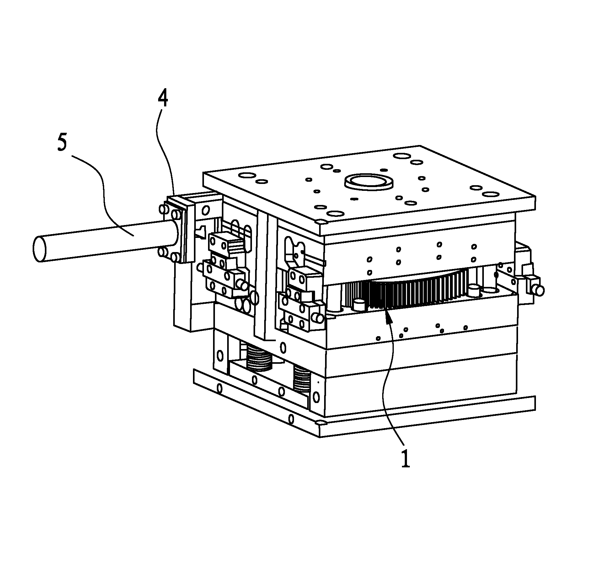
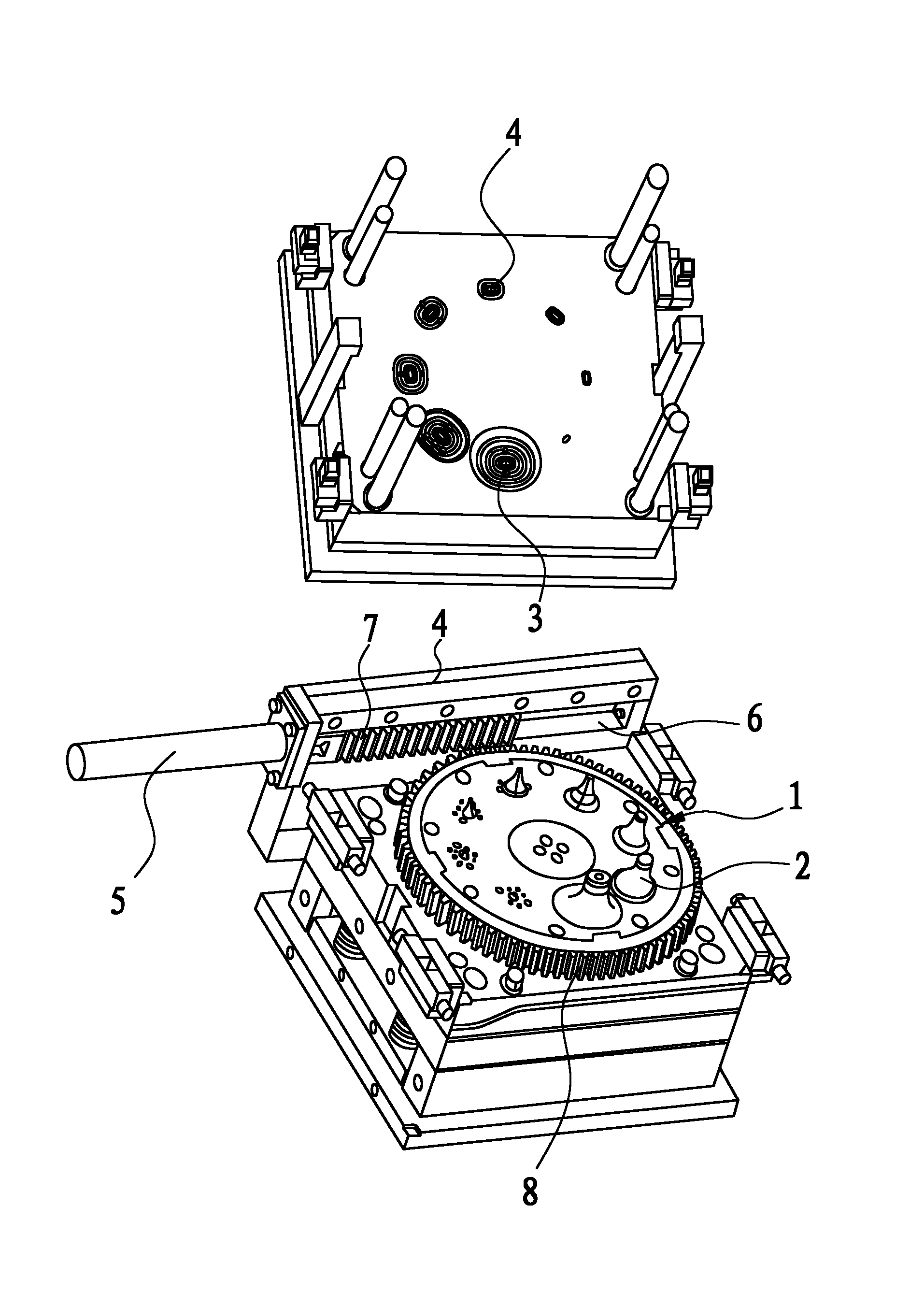
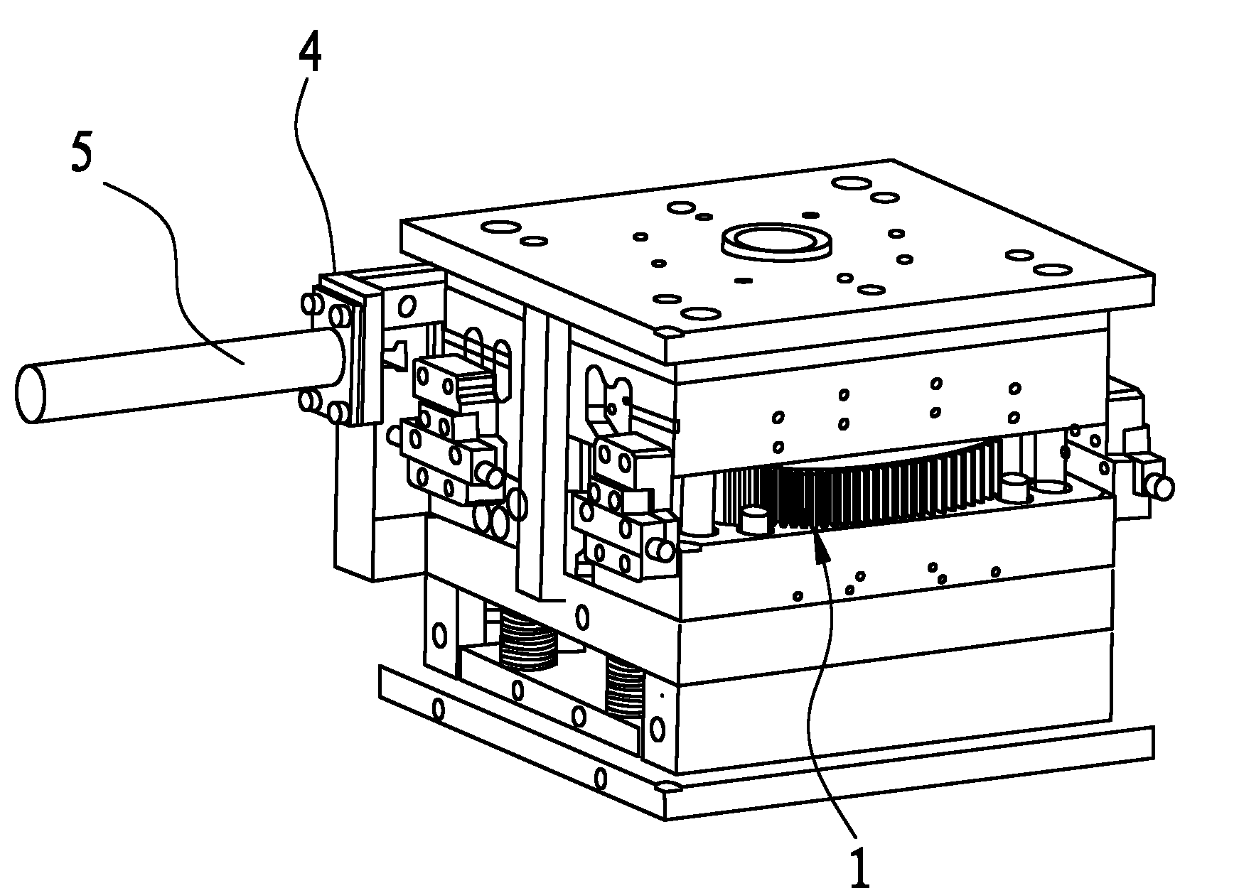
[0036] A rotary laminated injection mold, comprising a fixed mold overall and a movable mold overall, the fixed mold overall includes a fixed template and a fixed mold cavity, the movable mold overall includes a movable template, an ejection mechanism and a movable mold cavity, the The movable mold cavity is connected with a rotating disk 1, which rotates around the axis of the mold cavity, and a driving device for driving the rotating disk 1 is provided on one side of the mold. The ring of the rotating disk 1 is provided with at least two Set of inserts2. According to the specific thickness of the transparent product, it is divided into multiple equal parts, and each equal part is provided with an insert 2. Of course, the equal parts of the transparent product and the number of inserts 2 can be flexibly divided according to th...


PUM


Abstract

The invention relates to the technical field of an injection mould, and in particular relates to a rotating laminated type injection mould and an injection method using the same. The mould comprises a fixed mould main body and a movable mould main body, wherein the fixed mould main body comprises a fixed mould plate and a fixed mould chamber, the movable mould main body comprises a movable mould plate, an ejection mechanism and a movable mould chamber, the movable mould chamber is coupled with a rotating disk, one side of the mould is provided with a driving device which drives the rotating disk to rotate, the rotating disk is annularly provided with at least two embedding pieces which are set according to the thickness of a product, and the fixed mould chamber is provided with cavities which are matched with the embedding pieces. As the rotating disk rotates, the embedding pieces arranged at the rotating disk and the cavities arranged at the fixed mould chamber are closed, glued and cooled to be formed and opened, and the transparent product with the special thickness is divided to be subjected to alternated type or laminated type injection at least twice. The invention is reasonable in structure, the size of a mould blank is reduced, the indentation on the surface of the transparent product with the special thickness is controlled, the easily generated air bubble of an inner core is avoided, the injection period is shortened, and the production cost is reduced.

Description

technical field [0001] The invention relates to the technical field of injection molds, in particular to a rotary lamination injection mold and an injection molding method using the mold. Background technique [0002] At present, rotary devices are widely used in plastic injection molds. However, it has not been used on two-color molds for alternate, stacked injection molding, which is used to inject transparent products with a specific thickness. [0003] In the prior art, injection molding of transparent products with a specific thickness is generally divided into two categories, one is to design a set of molds for injection molding production, but because the product requires a specific thickness, in order to avoid surface depressions and product bubbles, injection molding needs Ensure the clamping force. Therefore, the mold volume needs to be increased, and the tonnage of the corresponding injection molding machine also needs to be increased. If the product requires a ...

Claims


Application Information

Patent Timeline
Patent Type & Authority Applications(China)
IPC IPC(8): B29C45/26
Inventor 陈锦华
Owner 毅昌金型(东莞)五金制品有限公司
Why Eureka
Try Eureka