
Plastic building template system

A technology of building templates and templates, which is applied in the field of building auxiliary materials, can solve the problems of leakage of castables, loose joints of inner joints, and low compressive strength of connectors, and achieve the effect of improving the tightness of the joint and increasing the strength

Active Publication Date: 2012-12-05
王亚运
View PDF1 Cites 0 Cited by
  • Summary
  • Abstract
  • Description
  • Claims
  • Application Information

AI Technical Summary

Problems solved by technology

[0005] The invention aims to solve the problem in the prior art that the pouring quality is affected by the leaking of the pouring material due to the incomplete bonding of the inner joints during pouring
[0006] In addition, it further solves the problem of low compressive strength of the joints in the corner of the building formwork system

Method used


Image

  • Plastic building template system
  • Plastic building template system
  • Plastic building template system

Examples


Embodiment Construction

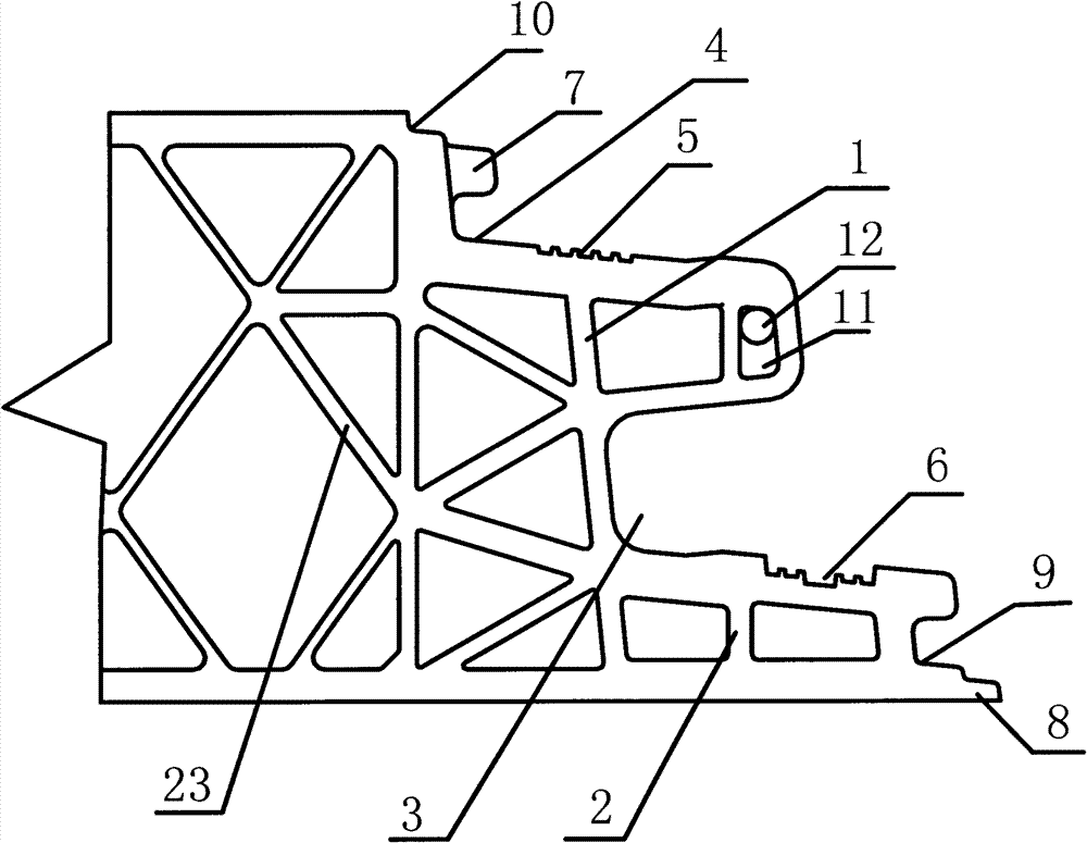
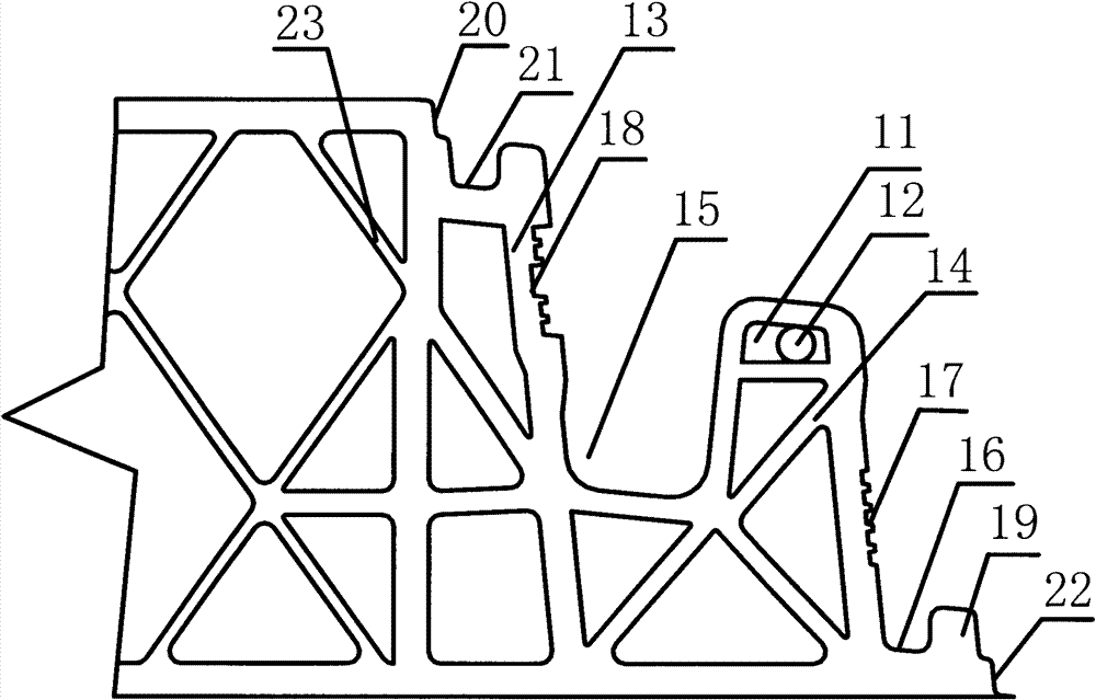
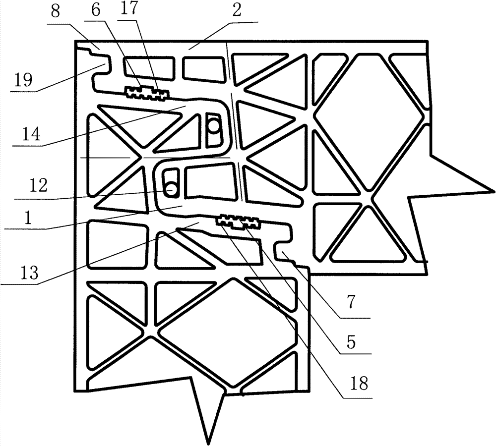
[0085] Combine figure 1 As shown, the present invention relates to a plastic building formwork system, which includes a first formwork spliced ​​with each other to form a flat formwork system. The first formwork has two panels and a reinforcing rib 23 connecting the two panels. A plane connector is formed on the splicing edge of the template, and the plane connector, viewed from the cross section of the first template, includes:

[0086] The first chuck 1 and the second chuck 2 protruding to the adjacent template, the side of the first chuck 1 away from the second chuck 2 is on the same plane as a panel of the first template;

[0087] The first card slot 3 located between the first card head 1 and the second card head 2 and the second card slot 4 located on the side of the first card head 1 away from the first card slot 3;

[0088] A first fixing groove 5 arranged on the side wall of the first chuck 1 away from the first groove 3 and a first fixing groove 5 arranged on the side wall ...


PUM


Abstract

The invention relates to a plastic building template system. The system comprises first templates which are spliced together to form a plane template system, and second templates which are spliced with the first templates to form corners, wherein, plane connecting heads are formed on spliced edges of the first templates; the second templates form corner connecting heads on spliced edges between the second templates and the first templates; and the plane connecting heads are coupled with the corner connecting heads so that seams of the building template system have higher strength and better binding tightness and meanwhile external surfaces of panels at two sides of the neighboring templates are respectively limited on the same plane at the same side, thus the surface of the building template system close to a grouting side is flat, and the surface flatness of the building after cast molding is ensured.

Description

Technical field [0001] The invention relates to the field of building auxiliary materials, in particular to a plastic building template system. Background technique [0002] Compared with previous building templates made of wood and steel, plastic building templates have the advantages of lighter weight, lower manufacturing cost, less environmental pollution, and easy installation and disassembly, and have been widely used in the construction industry. For example, CN2758370Y discloses a plastic construction template combination, which includes a plastic template, a plastic corner and a plastic chuck. The two sides of the outer plane of the plastic template are provided with longitudinal ridges. The plastic template is used for the template splicing of linear building surfaces, the plastic corner is used to connect the plastic template on both sides of the corner at the corner of the building surface, and the plastic chuck is used to clamp adjacent Adjacent longitudinal ridges a...

Claims


Application Information

Patent Timeline
Patent Type & Authority Patents(China)
IPC IPC(8): E04G9/05
Inventor 王亚运
Owner 王亚运
Learn More