
Pile-driving machinery and drilling bucket thereof

A technology for piling machinery and drilling buckets, which is applied in the direction of drill bits, drilling equipment, earthwork drilling and mining, etc. It can solve the problems of damage, inability to move, and occupy a large space, so as to improve opening efficiency, reduce structural size, and improve use. The effect of longevity

Inactive Publication Date: 2011-05-18
BEIJING SANY HEAVY MASCH CO LTD
View PDF4 Cites 4 Cited by
  • Summary
  • Abstract
  • Description
  • Claims
  • Application Information

AI Technical Summary

Problems solved by technology

[0006] In the above-mentioned rotary drilling rig, the opening of the drill bucket is realized by the push rod. Since the distance between the power end of the push rod and the bottom of the drill is relatively long, this requires the outer diameter of the push rod to be large enough to ensure that it has a high Bending strength, and the outer diameter of the push rod is larger, which occupies a larger space inside the drill bucket, which affects the smoothness of sand entering the drill bucket, and the utilization rate of steel is also very low. If the sand contains Larger rock blocks may cause the pressure rod to be stuck and unable to move; and if the outer diameter of the push rod is small, the push rod will be easily deformed and damaged, the failure rate of the drilling bucket is high, and the working stability is low

Method used


Image

  • Pile-driving machinery and drilling bucket thereof
  • Pile-driving machinery and drilling bucket thereof
  • Pile-driving machinery and drilling bucket thereof

Examples


Embodiment Construction

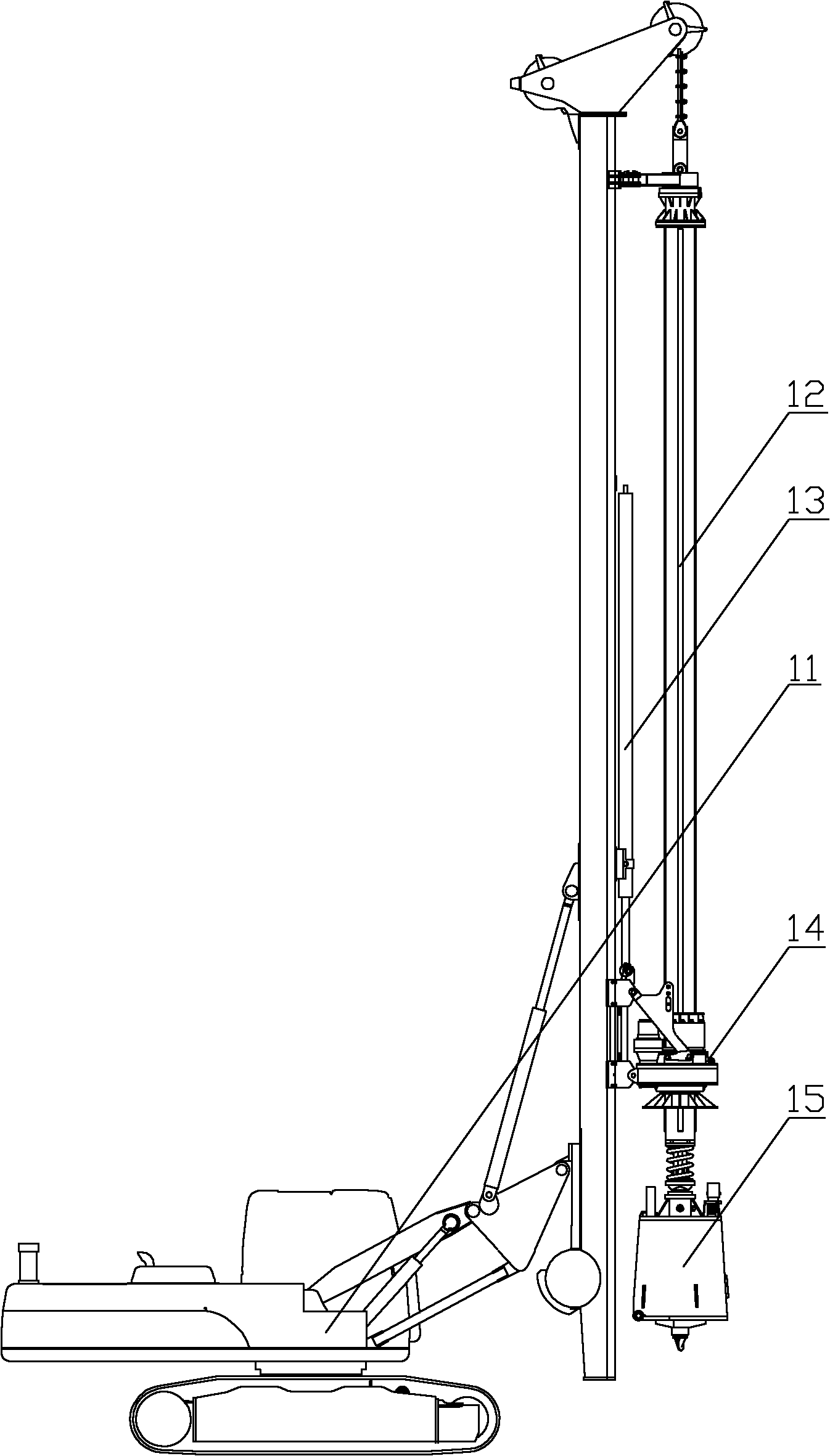
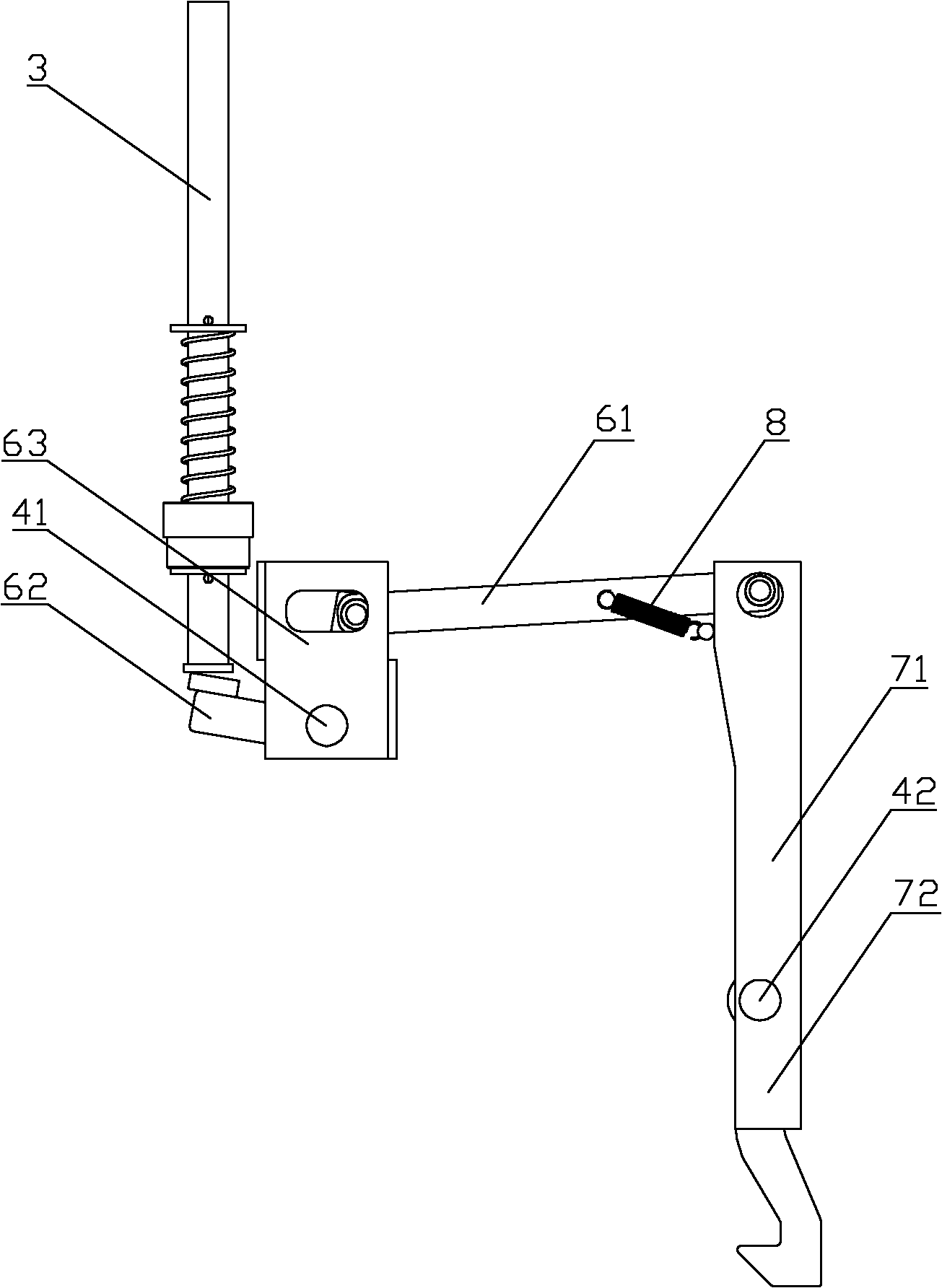
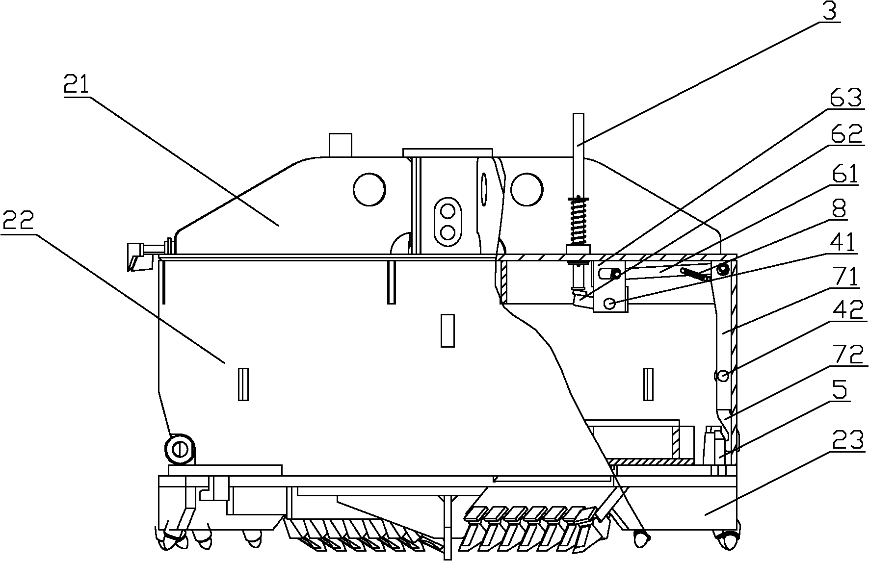
[0027] The core of the present invention is to provide a drilling bucket for piling machinery, which has high opening efficiency, low failure rate and high working stability. Another core of the present invention is to provide a piling machine comprising the above-mentioned drilling bucket.

[0028] In order to enable those skilled in the art to better understand the technical solutions of the present invention, the present invention will be further described in detail below in conjunction with the accompanying drawings and specific embodiments.

[0029] Please refer to figure 2 , image 3 and Figure 4 ; figure 2 It is a structural schematic diagram of a specific embodiment of the opening mechanism of the drilling bucket provided by the present invention; image 3 It is a structural schematic diagram of a drill bucket in a closed state in a specific embodiment provided by the present invention; Figure 4 for image 3 The schematic diagram of the drill bucket in the op...


PUM


Abstract

The invention provides a drilling bucket of pile-driving machinery. The drilling bucket comprises a drilling top and a pressure bar, wherein, the drilling top is connected with a drill stem of the pile-driving machinery, a cylinder is arranged on the lower end of the drilling top, and a drilling bottom is hinged on the lower end of the cylinder; the pressure bar passes through the drilling top along the axial direction of the cylinder, the top end of the pressure bar is contacted with or separated from an unlocking pressure plate and moves along the axial direction of the cylinder, and the bottom end of the pressure bar acts on a rocker arm mechanism; the rocker arm mechanism is arranged on the drilling top; one end of a pulling plate assembly is connected with the rocker arm mechanism, and the other end of the pulling plate assembly is connected with a lock hook assembly of a lock hook mechanism; the lock hook assembly is hinged with the cylinder through a second hinged shaft; and the tail end of the lock hook assembly is selectively connected with a fastener of the drilling bottom. The drilling bucket has the advantages that as components mainly bear tension action during the process of opening the drilling bucket, the needed rigidity of the components is smaller, and the structural size of the components can be correspondingly reduced, thus improving the volumetric efficiency of the drilling bucket, avoiding damage caused by deformation of the components under the action of compressive stress owing to insufficient rigidity, and prolonging the service life of the drilling bucket. The invention further discloses the pile-driving machinery comprising the drilling bucket.

Description

technical field [0001] The invention relates to the technical field of machinery, in particular to a drilling bucket used for pile driving machinery. The present invention also relates to a piling machine comprising the above-mentioned drilling bucket. Background technique [0002] With the rapid development of my country's economic construction, the market demand for various pile machinery is increasing. [0003] The construction process of modern construction projects generally begins with pile foundation construction. Therefore, pile hole construction is particularly important. Taking rotary drilling rigs as an example, during the construction process of rotary drilling rigs, you can choose according to the differences in geological conditions encountered. Using various drilling tools, such as various drill bits or drilling buckets, the rotary drilling rig needs to export the drilling slag in the drilling bucket after drilling for a period of time, and at this time, the ...

Claims


Application Information

Patent Timeline
IPC IPC(8): E21B10/00
Inventor 陈朝晖水俊峰王磊
Owner BEIJING SANY HEAVY MASCH CO LTD
Learn More