
Direct current protection test device and test method of direct current protector

A technology of DC protection and testing device, applied in the direction of measuring device, measuring electricity, measuring electrical variables, etc., can solve the problems of difficult control of output voltage value accuracy, inability to output multiple fiber quantities at the same time, etc., to achieve convenient experimental means, high practicality sexual effect

Inactive Publication Date: 2011-05-18
CSG EHV POWER TRANSMISSION
View PDF3 Cites 11 Cited by
  • Summary
  • Abstract
  • Description
  • Claims
  • Application Information

AI Technical Summary

Problems solved by technology

[0004] The test method of this kind of DC protection device in the prior art needs to manually adjust the DC power supply box and use a multimeter to measure the voltage. Therefore, every time the voltage is adjusted to the experimental value, a careful adjustment process is required, and It is difficult to control the accuracy of the output voltage value
In addition, in the prior art, only one channel can be added for each test, so it is impossible to output multiple optical fiber quantities at the same time

Method used


Image

  • Direct current protection test device and test method of direct current protector
  • Direct current protection test device and test method of direct current protector
  • Direct current protection test device and test method of direct current protector

Examples


Embodiment Construction

[0014] The solution of the present invention will be described in detail below by taking one of the specific implementations of the DC protection testing device and the DC protection testing method of the present invention as an example.

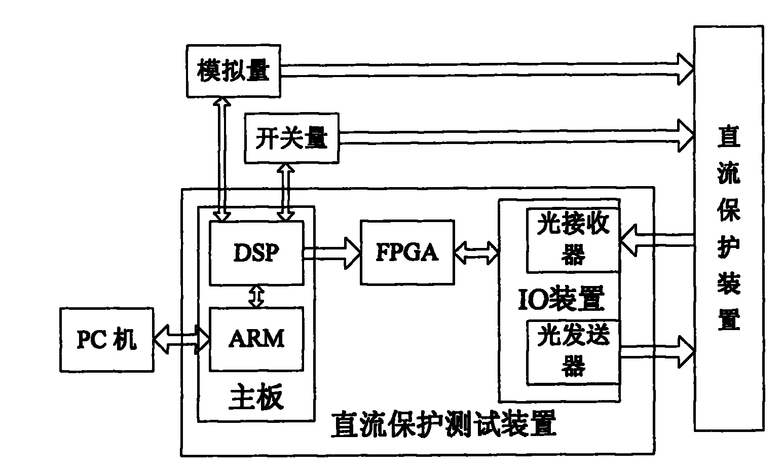
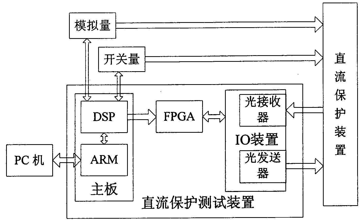
[0015] The fundamental purpose of the solution of the present invention is to improve the test accuracy when testing the DC protection device, and to improve the convenience when testing the DC protection device. For this reason, the solution of the present invention considers setting the DC protection test device, The DC protection test device can form a closed loop with the DC protection device to be tested, so that the test information can be directly sent to the DC protection device, and the DC protection test device can also receive the corresponding test data issued by the upper PC, such as voltage value, current value, and send the test data issued by the PC to the DC protection device, so that the digital test data can be set through ...


PUM


Abstract

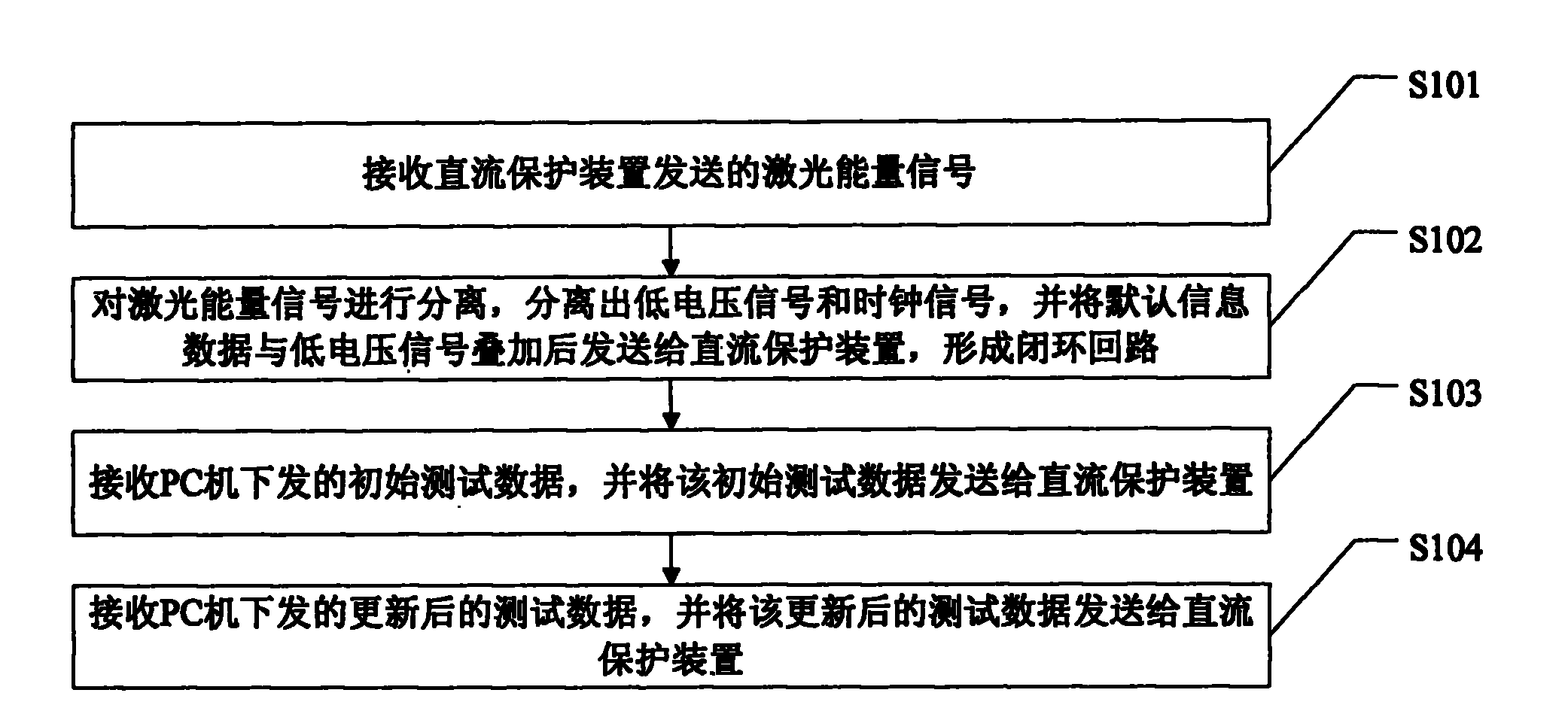
The invention discloses a direct current protection test device and a test method of a direct current protector. The device comprises an input and output (IO) device connected with the direct current protector, a mainboard device connected with an upper personal computer (PC) and the direct current protector, and a field programmable gate array (FPGA) connected between the mainboard device and the IO device, wherein the IO device receives a laser energy signal of the direct current protector, separates the received laser energy signal to acquire a clock signal and a low voltage signal and transmits the acquired signals to the FPGA; the FPGA superposes default information data with the low voltage signal according to a coded format and transmits a superposed signal to the direct current protector through the IO device; a closed loop is formed; the mainboard device receives test data transmitted by the upper PC and transmits the test data to the IO device through the FPGA; and the test data is transmitted to the direct current protector through the IO device. By using the direct current protection test device and the test method of the direct current protector, the test data can be precisely set, accurate and strict detection is performed on the direct current protector, a convenient experimental means is provided for the conventional test, and high practicability is achieved.

Description

technical field [0001] The invention relates to the field of testing high-voltage direct current transmission systems, in particular to a direct current protection test device and a test method for the direct current protection device. Background technique [0002] The control and protection system of the DC project of China Southern Power Grid is usually realized based on the high-speed digital programmable controller SIMADYND system. The DC control system is divided into two sets of mutually redundant systems. During this period, a bumpless switchover between the two systems is possible. The DC protection system adopts a two-out-of-three configuration. Three sets of DC protection devices with the same configuration are placed in three independent cabinets. The measured DC operating volume is directly taken from the primary circuit through optical fibers. Two sets of redundant protection, the AC filter protection part adopts the SIMADYND system. [0003] Due to the partic...

Claims


Application Information

Patent Timeline
Patent Type & Authority Applications(China)
IPC IPC(8): G01R31/00
Inventor 陈立向前
Owner CSG EHV POWER TRANSMISSION
Learn More