Rectification circuit for radio frequency electronic tags

A technology of electronic tags and rectification circuits, which is applied in the field of rectification circuits and rectification circuits of radio frequency electronic tags. It can solve the problems of low signal utilization rate and reduced rectification efficiency, so as to improve utilization rate, reduce negative impact and stabilize gate voltage. Effect

Inactive Publication Date: 2011-05-18
SHANGHAI ADVANCED RES INST CHINESE ACADEMY OF SCI
View PDF3 Cites 11 Cited by
  • Summary
  • Abstract
  • Description
  • Claims
  • Application Information

AI Technical Summary

Problems solved by technology

[0008] In order to overcome the problems of low signal utilization and low rectification efficiency due to the absence of a stable circuit in the above-mentioned prior art, an object of the present invention is to provide a rectification circuit for radio frequency electronic tags to achieve a full-wave Rectifier circuit to improve signal utilization

Method used


Image

  • Rectification circuit for radio frequency electronic tags
  • Rectification circuit for radio frequency electronic tags
  • Rectification circuit for radio frequency electronic tags

Examples


Embodiment Construction

[0025] The implementation of the present invention will be described below through specific examples and in conjunction with the accompanying drawings, and those skilled in the art can easily understand other advantages and effects of the present invention from the content disclosed in this specification. The present invention can also be implemented or applied through other different specific examples, and various modifications and changes can be made to the details in this specification based on different viewpoints and applications without departing from the spirit of the present invention.

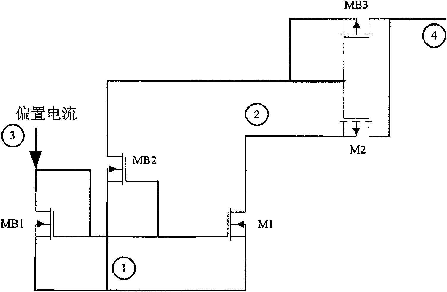
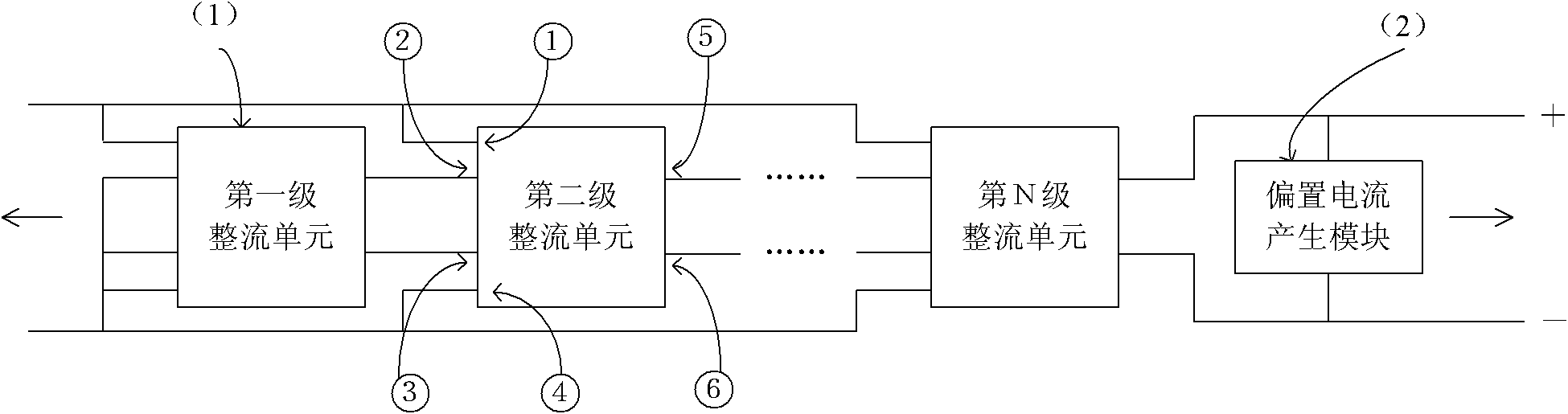
[0026] image 3 It is the circuit structure diagram of the preferred embodiment of the rectification circuit used in the radio frequency electronic tag of the present invention, Figure 4 It is a circuit structure diagram of a single-stage rectification unit in a preferred embodiment of the rectification circuit for radio frequency electronic tags of the present invention. Please also...


PUM


Abstract

The invention discloses a rectification circuit for radio frequency electronic tags. The rectification circuit at least comprises N rectifying units, and each of the rectifying units is in a difference structure, thus full-wave rectification for signals is implemented and the utilization rate of the signals is increased, in addition, a bias voltage is offered to grids of rectifying tubes by arranging a bias voltage generating tube so that all the rectifying tubes are in a subthreshold state, and meanwhile, a grid stabilization capacitor is used for reducing the impact from grid-source parasitic capacitances of the rectifying tubes, thereby stabilizing a grid voltage and reducing the impact on the bias voltages of the grids, caused by the fluctuation of a source signal.

Description

technical field [0001] The invention belongs to the field of radio frequency integrated circuits, and relates to a rectification circuit, in particular to a rectification circuit for radio frequency electronic tags. Background technique [0002] Radio Frequency Identification (RFID) is a non-contact automatic identification technology. Its basic principle is to use radio frequency signals and spatial coupling transmission characteristics to automatically identify target objects and obtain relevant information to achieve automatic identification. As a key technology, RFID has attracted more and more people's attention due to its many convenient features and wide application fields. RFID technology has a very broad application prospect. It can be applied to various fields such as warehouse management, identification, transportation, food medical treatment, animal management, access control and anti-theft, and industrial military in logistics and warehousing. It has brought gre...

Claims


Application Information

Patent Timeline
Patent Type & Authority Applications(China)
IPC IPC(8): G06K19/077H02M7/25
Inventor 刘理
Owner SHANGHAI ADVANCED RES INST CHINESE ACADEMY OF SCI
Why Eureka
Try Eureka