Circular leaky waveguide cable

A circular waveguide and leaky technology, applied in leaky waveguide antennas, waveguides, waveguide-type devices, etc., can solve the problems of increased loss of inner conductor and its filling medium, uneven longitudinal distribution of radiation field waveguides, and decreased power capacity, etc. There is no communication blind area, it is not easy to interfere with external signals, and the effect of reducing loss

Active Publication Date: 2011-05-18
BEIJING JIAOTONG UNIV
View PDF3 Cites 20 Cited by
  • Summary
  • Abstract
  • Description
  • Claims
  • Application Information

AI Technical Summary

Problems solved by technology

[0003] The structure of a typical leaky coaxial cable is mainly composed of four parts: the inner conductor, the insulating layer, the outer conductor with slots and the sheath; in this way, as the transmission frequency increases, the inner conductor of the leaky coaxial cable and its filling The loss of the medium also increases accordingly; at the same time, due to the limitation of the structure, the power capacity decreases, so the existing leaky coaxial cables are generally suitable for the decimeter wave band, such as the frequency band of 300M ~ 3000M
[0004] Aiming at the defect of the existing leaky coaxial cable, a circular waveguide is proposed, which can be applied to the transmission of the UHF band; however, since the circular waveguide has a magnetic field component in the propagation direction and no electric field component When the TE wave is used, when the processing of the circular waveguide is not perfect or there is a slight inhomogeneity in the circular waveguide, the polarization plane of the main wave type TE11 field structure is prone to rotation, which causes the radiation field along the waveguide Longitudinal distribution is uneven, so circular waveguides are generally not used for long-distance transmission of RF energy and signals

Method used


Image

  • Circular leaky waveguide cable
  • Circular leaky waveguide cable
  • Circular leaky waveguide cable

Examples


Embodiment Construction

[0034] In order to make the above objects, features and advantages of the present invention more comprehensible, the present invention will be further described in detail below in conjunction with the accompanying drawings and specific embodiments.

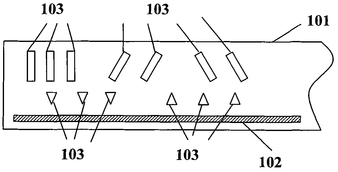
[0035] refer to figure 1 , shows the structural diagram of Embodiment 1 of a circular leaky waveguide cable according to the present invention, which may specifically include a circular waveguide wall 101, wherein a metal wire 102 is added inside the circular waveguide wall 101 along its axis direction , and, on the circular waveguide wall 101, a plurality of slot arrays 103 are evenly spaced along the axis direction.

[0036] First, the function of the metal wire 102 is discussed.

[0037] When there is no metal wire 102 in the circular waveguide, the boundary conditions of the circular leaky waveguide cable are rotationally symmetric, and the field distribution of the TE11 wave type electric field when the polarization plane is...


PUM


Abstract

The invention provides a circular leaky waveguide cable which comprises a circular waveguide wall and a metal wire and is characterized in that the metal wire is additionally arranged on a circular waveguide inner cavity along the axis direction of the circular waveguide inner cavity, and a plurality of gaps are uniformly arranged on the circular waveguide wall along the axis direction at intervals to form a gap array. The invention can be applied to high-frequency, microwave and high-power systems and realize that the polarized surface of a transmission wave field structure is not deflected with distance.

Description

technical field [0001] The invention relates to the technical field of communication cables, in particular to a circular leaky waveguide cable. Background technique [0002] At present, leaky coaxial cables are mainly used in tunnels, tunnels, underground railways, underground buildings and other environments where radio signals are poorly propagated. They can transmit the main energy and only radiate a small part within a certain range around the cable during transmission. Energy, forming a radio wave channel with limited radial range, can extend the range of radio waves with limited energy, thereby improving communication quality. [0003] The structure of a typical leaky coaxial cable is mainly composed of four parts: the inner conductor, the insulating layer, the outer conductor with slots and the sheath; in this way, as the transmission frequency increases, the inner conductor of the leaky coaxial cable and its filling The loss of the medium also increases accordingly;...

Claims


Application Information

Patent Timeline
Patent Type & Authority Applications(China)
IPC IPC(8): H01P3/06H01Q13/22
Inventor 王均宏张冲李雨键陈美娥张展
Owner BEIJING JIAOTONG UNIV
Why Eureka
Try Eureka