
Rotor structure of resonant type permanent magnet linear generator

A permanent magnet linear and resonant technology, applied in the field of batteries, linear generators, and charging devices, can solve problems such as difficulty in functioning, high precision requirements, and complex implementation, and achieve easy portability, simple equipment design, and small structure. Effect

Inactive Publication Date: 2011-05-18
麦伟仪 +1
View PDF6 Cites 10 Cited by
  • Summary
  • Abstract
  • Description
  • Claims
  • Application Information

AI Technical Summary

Problems solved by technology

However, the directional accuracy of such a generator requires high precision and complex implementation, and the generated power is small. Usually, the power generated in three or four hours is not enough for five minutes, and it is difficult to play a role in practical applications.

Method used


Image

  • Rotor structure of resonant type permanent magnet linear generator
  • Rotor structure of resonant type permanent magnet linear generator
  • Rotor structure of resonant type permanent magnet linear generator

Examples


Embodiment Construction

[0040] A generator and a charging device provided by the present invention will be described in detail below with reference to the drawings and specific embodiments.

[0041] Most of the existing portable generator charging devices are hand-operated generators. When charging portable electrical appliances and electronic products, it is necessary to turn the generator charging device by hand for at least 30 minutes before the electronic and electrical products can be used for a certain period of time. power consumption. The purpose of the present invention is to provide an external power generation and charging device applied to milliamp level electronic appliances or directly embedded in the electronic appliances.

[0042] figure 1 shows a charging device with a resonant permanent magnet linear generator, such as figure 1 As shown, the charging device includes a permanent magnet linear generator, an electronic control system, a supercapacitor circuit and a battery. Among th...


PUM


Abstract

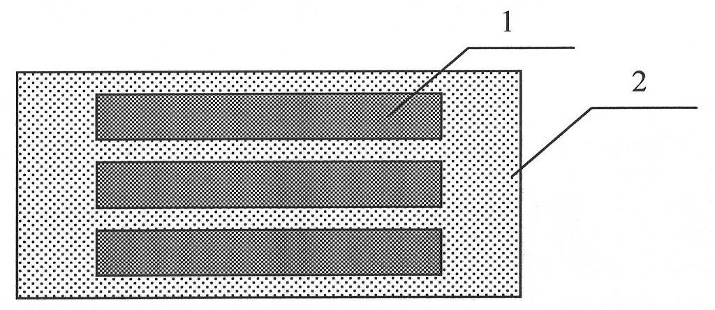
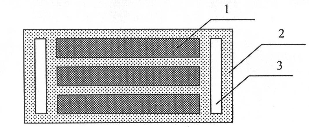
The invention provides a rotor structure of a resonant type permanent magnet linear generator, comprising permanent magnet materials and non-conductive materials coating the permanent magnet materials, wherein the permanent magnet materials are in a strip, block or elliptical block shape formed by two or more alternate blocks of non-conductive materials and are uniformly arranged in the non-conductive materials; the rotor structure further comprises chute structures; substrates made of the non-conductive materials are positioned between the rotor structures; each chute structure comprises a reversing spring, a resonant spring, a U-shaped chute and a roll ball; the roll ball is arranged in the U-shaped chute; the substrates are clamped in the U-shaped grooves; the end parts of the substrates are contacted with the roll balls and slide in the U-shaped grooves up and down; two ends of the two U-shaped chutes are correspondingly connected by a connecting plate; the reversing springs are respectively arranged at two ends of each of the two U-shaped chutes; and the resonant springs are respectively arranged between the substrates and two connecting plates.

Description

technical field [0001] The invention relates to magnet power generation technology, more specifically, the invention relates to a linear generator, a charging device and a battery. Background technique [0002] Generally, portable electronic devices such as mobile phones, portable audio and video players, digital cameras, headlamps, etc. all require their own batteries to be used when they are away from an external power source. The batteries are generally made of precious metals such as nickel-cadmium and lithium batteries, which are expensive, difficult to recycle, and cause irreversible damage to the environment. Generally speaking, a charging connector is provided on the portable electronic device, and the portable electronic device is charged by connecting an external power source or an external charger through the connector without taking out the battery. [0003] For portable electronic devices, commercial power is usually used as an external power supply, but it is ...

Claims


Application Information

Patent Timeline
IPC IPC(8): H02K35/02H02J7/32H02J15/00
Inventor 麦伟仪陈坚
Owner 麦伟仪
Learn More