Delay compensation method for network control system

A technology of network control system and delay compensation, applied in the direction of transmission system, digital transmission system, electrical components, etc., can solve problems such as deterioration of system control performance quality, system failure, large economic investment, etc.

Inactive Publication Date: 2011-05-18
HAINAN UNIVERSITY
View PDF1 Cites 5 Cited by
  • Summary
  • Abstract
  • Description
  • Claims
  • Application Information

AI Technical Summary

Problems solved by technology

[0007] Due to the network delay τ in the denominator of the closed-loop transfer function shown in equation (1) 1 and τ 2 index term of and The existence of time delay will deteriorate the control performance quality of the system, and even cause the system to lose stability, and in severe cases, the system may fail.
[0008] The key to reducing the impact of delay on system stability is whether the network delay τ between the transmitter node and the controller node can be realized 2 index term of and the network delay τ between the controller node and the actuator node 1 index term of It is removed from the denominator of equation (1), that is, the closed-loop characteristic equation does not contain all the exponential terms of the network delay, and then realizes the compensation for the network delay. However, to realize the compensation for the network delay, it must first Know the size of the network delay. At present, the method commonly used at home and abroad is to measure the network delay τ 1 and τ 2 measurement to compensate for the impact of delay on system stability. However, since the accurate measurement of network delay needs to meet the requirements of node clock signal synchronization, if hardware is used to achieve complete synchronization of node clock signals, a large economic investment; if the clock signal is corrected by software, it may be affected by network delay when the correction signal is transmitted between nodes, and it is difficult to achieve complete synchronization of the node clock; if the method of estimating, identifying or predicting network delay is used to obtain To determine the size of the network delay, it is necessary to know the exact probability distribution of the network delay, or an accurate mathematical model, but because the size of the network delay may be random or time-varying, its value is not related to the specific network protocol, Depending on factors such as the size of the network load and the network topology, there may be deviations in the estimation or identification of the network delay.

Method used


Image

  • Delay compensation method for network control system
  • Delay compensation method for network control system
  • Delay compensation method for network control system

Examples


Embodiment Construction

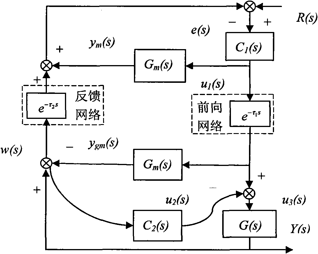
[0083] The following will refer to the attached image 3 Exemplary embodiments of the present invention are described in detail to make the above and other features and advantages of the present invention more apparent to those skilled in the art.

[0084] The specific implementation steps are as follows:

[0085] The first step: the transmitter node working in the time-driven mode estimates the output signal Y(s) of the controlled pair G(s) and the predicted modulus G of the controlled object m (s) output signal y gm (s) is periodically sampled, and Y(s) and y gm (s) implement the subtraction operation to obtain the model deviation signal w(s); and transmit w(s) to the controller node through the feedback network path;

[0086] Step 2: The controller node working in the event-driven mode is triggered by the feedback network path signal w(s), and the given signal R(s) is connected with w(s) and y m (s) implement the subtraction operation to obtain the error signal e(s); im...


PUM


Abstract

The invention provides a delay compensation method for a network control system, belonging to the technical field of network control systems. True network data transmission processes from a transmitter node to a controller node and from the controller node to an actuator node are adopted in the method to replace network delay compensation models between the transmitter node and the controller node and between the controller node and the actuator node, thereby omitting measurement, estimation or identification on network data transmission delay between nodes and also avoiding the requirement on the node clock signal synchronicity. When an offset exists between an estimated model of a controlled object and a true model, a model offset correction controller can enhance the robustness and theantijamming capability of a system. By adopting the method, the influence of delay on the stability of the system can be lowered and the quality of the control performance of the system can be improved. The method is suitable for sectional, real-time, on-line and dynamic compensation and control on the delay of a network control system of which the network exists between the transmitter node and the controller node and between the controller node and the actuator node and of which the mathematical model of the controlled object is known or incompletely known.

Description

technical field [0001] The invention relates to a network control system, in particular to a delay compensation method for a network control system with long delay, and belongs to the technical field of network control systems. Background technique [0002] In the distributed control system, the closed-loop feedback control system formed by the real-time communication network between the transmitter and the controller, and the controller and the actuator is called a networked control system (Networked control systems, NCS), which is applicable to the network of the present invention The typical structural block diagram of the control system is as follows: figure 1 shown. [0003] Compared with the traditional point-to-point structure control system, the network control system has the advantages of low cost, easy information sharing, easy expansion and maintenance, and great flexibility. It has been widely used in industrial control processes in recent years. However, due to...

Claims


Application Information

Patent Timeline
Patent Type & Authority Applications(China)
IPC IPC(8): H04L7/00H04L7/033
Inventor 杜锋杜文才
Owner HAINAN UNIVERSITY
Why Eureka
Try Eureka