Compensation method for external feedback and internal loop randomness network time delay of network cascade control system

A cascading control and network delay technology, applied in the field of network control systems, can solve problems such as large economic investment, system loss of stability, and difficulties in control system analysis and design

Inactive Publication Date: 2011-04-27
HAINAN UNIVERSITY
View PDF2 Cites 1 Cited by
  • Summary
  • Abstract
  • Description
  • Claims
  • Application Information

AI Technical Summary

Problems solved by technology

[0008] (2) The network delay that occurs in the process of transmitting network data from the previous node to the next node, no matter what prediction or estimation method is used in the previous node, it is impossible to know in advance the subsequent network delay Accurate value. Time delay leads to system performance degradation and even system instability, and also brings difficulties to the analysis and design of the control system.
[0013] Since the denominator of the closed-loop transfer function shown in equation (1) includes the network delay τ 1 , τ 2 and τ 3 index term of and The existence of time delay will deteriorate the control performance quality of the system, and even cause the system to lose stability, and in severe cases, the system may fail.
[0014] The key to reducing the impact of delay on system stability is whether the random network delay τ 1 , τ 2 and τ 3 index term of and It is removed from the denominator of equation (1), that is, the exponential term of all network delays is not included in the closed-loop characteristic equation of the system, and then the compensation of network delay is realized. However, to realize the compensation of network

Method used


Image

  • Compensation method for external feedback and internal loop randomness network time delay of network cascade control system
  • Compensation method for external feedback and internal loop randomness network time delay of network cascade control system
  • Compensation method for external feedback and internal loop randomness network time delay of network cascade control system

Examples


Embodiment Construction

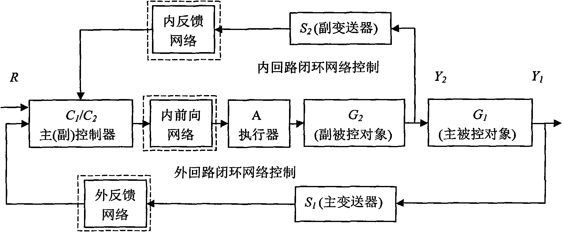
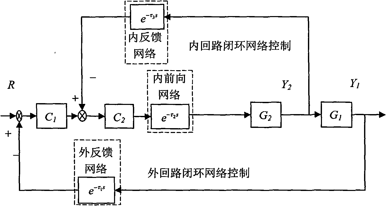
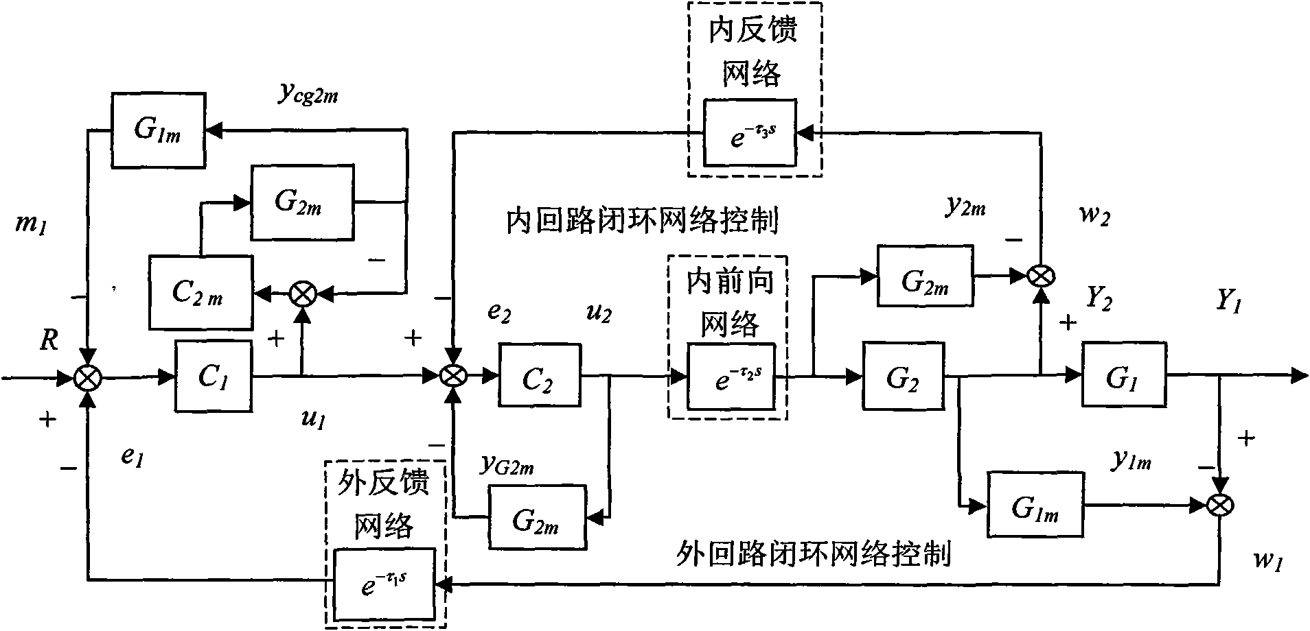
[0101] The following will refer to the attached image 3 Exemplary embodiments of the present invention are described in detail to make the above and other features and advantages of the present invention more apparent to those skilled in the art.

[0102] The specific implementation steps are as follows:

[0103] The first step: the main transmitter node working in the time-driven mode to the main controlled object G 1 (s) output signal Y 1 (s) and its prediction model G lm (s) output signal y 1m (s) Periodic sampling (the sampling period is h 1 ), and for Y 1 (s) and y 1m (s) Implement the subtraction operation to obtain the model error signal w 1 (s);

[0104] Step 2: The main transmitter node will w 1 (s) transmitted to the primary (secondary) controller node through the external loop feedback network path;

[0105] Step 3: The sub-transmitter node working in the time-driven mode is connected to the sub-controlled object G 2 (s) output signal Y 2 (s) and its pr...


PUM


Abstract

The invention provides a compensation method for external feedback and internal loop randomness network time delay of a network cascade control system, belonging to the technical field of network control systems. In the invention, a network time delay compensation model is replaced by utilizing an actual network data transmission process between an external feedback network path node and an internal loop network path node of the network cascade control system, measurement, observation, estimation or identification of network data transmission randomness time delay between the nodes is avoided, and the requirement on the clock signal synchronism of the nodes is eliminated. By utilizing the method, the influence of a randomness network time delay on the system stability can be reduced, and the control performance quality of the system is improved. The compensation method is suitable for the dynamic compensation and control of the randomness network time delay of the network only existing in the external feedback and internal loop network paths of the network cascade control system when a main controlled object mathematical model and an auxiliary controlled object mathematical model are known.

Description

technical field [0001] The invention relates to a method for compensating the random network time delay of external feedback and internal loop network paths in a network cascade control system, belonging to the technical field of network control systems. Background technique [0002] The closed-loop feedback control system composed of nodes such as transmitters, controllers and actuators through a real-time communication network is called a networked control system (Networked Control Systems, NCS). Networked control systems first appeared in 1998 in the treatise of Walsh, University of Maryland, USA At that time, the structure of the networked control system was only illustrated by means of diagrams. Compared with the traditional point-to-point structure system, the networked control system has the advantages of low cost, easy information sharing, easy expansion and maintenance, and great flexibility. It has been widely used in industrial control over the years. However, due...

Claims


Application Information

Patent Timeline
IPC IPC(8): G05B19/418H04L7/00
CPCY02P90/02
Inventor 杜锋杜文才
Owner HAINAN UNIVERSITY
Why Eureka
Try Eureka