Textile machine having a moveable service unit

A technology for service components and textile machines, applied in spinning machines, textiles and papermaking, thin material processing, etc., can solve the problems of inaccurate positioning and ineffectiveness, and achieve the effect of improving reliability, simple and reliable control

Active Publication Date: 2013-03-13
SAURER GERMANY GMBH & CO KG
View PDF3 Cites 0 Cited by
  • Summary
  • Abstract
  • Description
  • Claims
  • Application Information

AI Technical Summary

Problems solved by technology

On the one hand, the yarn path may vary at least slightly, which leads to imprecise positioning
On the other hand, this method does not work if there are two broken yarns at adjacent stations
Therefore an additional positioning mechanism is required

Method used


Image

  • Textile machine having a moveable service unit
  • Textile machine having a moveable service unit
  • Textile machine having a moveable service unit

Examples


Embodiment Construction

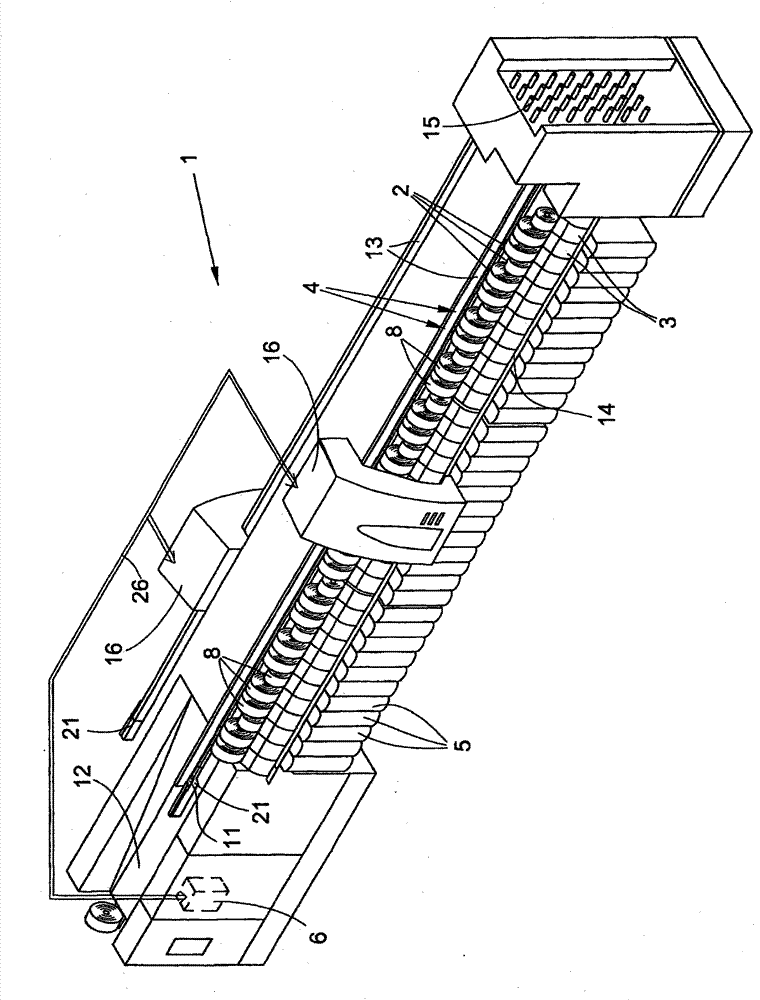
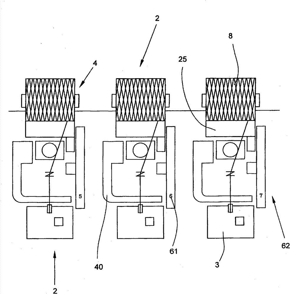
[0035] figure 1 An open-end spinning machine 1 is shown having a plurality of stations 2 each equipped with an open-end spinning device 3 and a winding mechanism 4 . The open-end spinning machine 1 also has two identical service assemblies 16 .

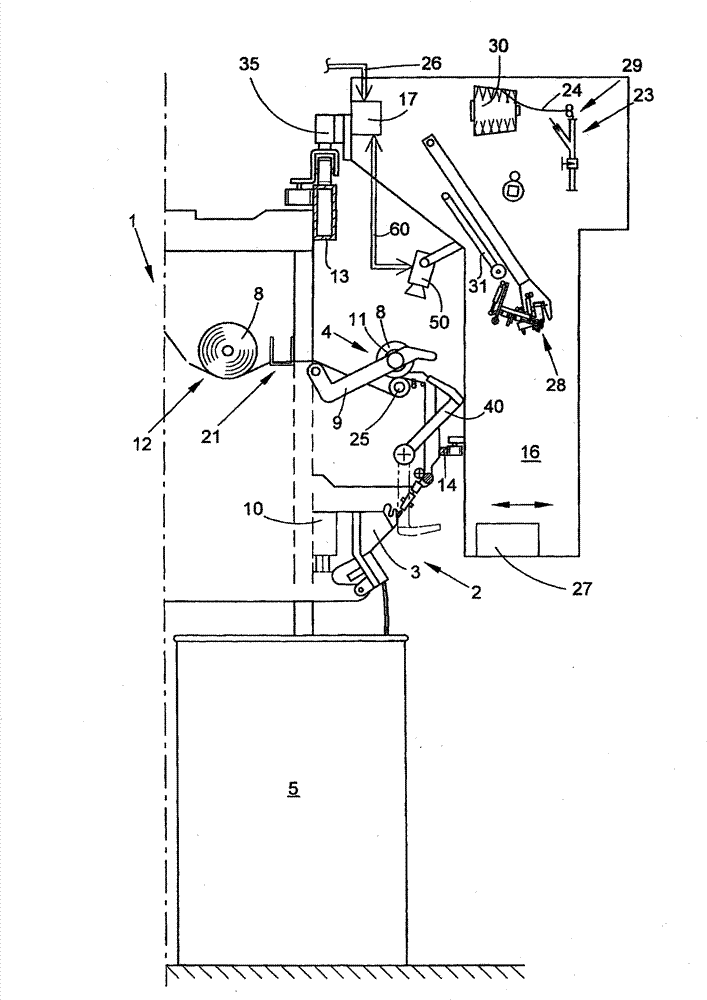
[0036] In the spinning device 3 , the fiber strip fed in the spinning pot 5 is spun into a yarn which is wound up on the winder 4 to form a cross-wound bobbin 8 . like figure 2 As shown, the winding mechanism 4 is equipped with a creel 9 to rotatably hold an empty bobbin 11 or a cross-wound bobbin 8, and a winding drum 25 to rotate these elements. The open-end spinning machine 1 also has a central control unit 6 which is connected via a bus system 26 to a station-specific control mechanism 10 . Furthermore, a textile machine 1 of this type has an empty bobbin feeder, which essentially consists of an empty bobbin cassette 15 and a bobbin transport 12 for the processed cross-wound bobbins 8 . The pipe supply path 21 is composed.

...


PUM


Abstract

The invention relates to a textile machine (1) having a plurality of work stations (2) and at least one service unit (16) that can be moved along the work stations (2) for operating and / or maintaining the individual work stations (2), wherein the at least one service unit (16) comprises at least one camera (50), and wherein the camera (50) is designed to produce images that include components of the service unit (16) and / or the work stations (2) and to transmit them to a control unit (17, 6, 10) of the textile machine (1) for detecting and evaluating the components and / or the current absolute or relative positions thereof, said control unit using the information obtained for controlling the service unit (16) and / or the work station (2) requiring operation and / or control. The invention further relates to a method for operating a textile machine (1) of said kind.

Description

technical field [0001] The invention relates to a textile machine having a plurality of work stations and at least one service assembly movable along the work stations to operate and / or maintain the respective work stations. The invention also relates to a method for operating a textile machine. Background technique [0002] A textile machine of this type can be, for example, an open-end spinning machine, in particular a rotor spinning machine. In this case, the yarn is spun from a fiber band in the spinning rotor, withdrawn from the spinning rotor by a yarn withdrawal tube, and then wound on bobbins, in particular cross-wound bobbins. Service assemblies for spinning machines of this type have long been known. These service components can be moved along the stations and, if necessary, temporarily used at one of the stations. Depending on the station configuration, the service components can take on various tasks, for example splicing after yarn breaks or package changes. ...

Claims


Application Information

Patent Timeline
Patent Type & Authority Patents(China)
IPC IPC(8): D01H13/00
CPCD01H15/013D01H13/005B65H2701/31B65H54/26
Inventor 海因茨-迪特尔·戈培尔欧文·彼得斯
Owner SAURER GERMANY GMBH & CO KG
Why Eureka
Try Eureka