
Method for mounting a bush around a part of a shaft by means of a tight fitting

A one-part and bushing technology, which is applied to the rigid support of bearing components, bearings, couplings, etc., can solve the problems of difficult mass production and high cost, and achieve the effect of saving time and benefiting stability

Active Publication Date: 2011-05-18
ATLAS COPCO AIRPOWER NV
View PDF11 Cites 11 Cited by
  • Summary
  • Abstract
  • Description
  • Claims
  • Application Information

AI Technical Summary

Problems solved by technology

[0014] The disadvantage of such conical embodiments is that they are expensive
[0015] Even when the element is made, for example, of fiber-reinforced composite material, it would be difficult to mass-produce due to the conical shape of the element

Method used


Image

  • Method for mounting a bush around a part of a shaft by means of a tight fitting
  • Method for mounting a bush around a part of a shaft by means of a tight fitting
  • Method for mounting a bush around a part of a shaft by means of a tight fitting

Examples


Embodiment Construction

[0062] The present invention relates to a method of installing a bushing on a portion of a shaft using an interference fit.

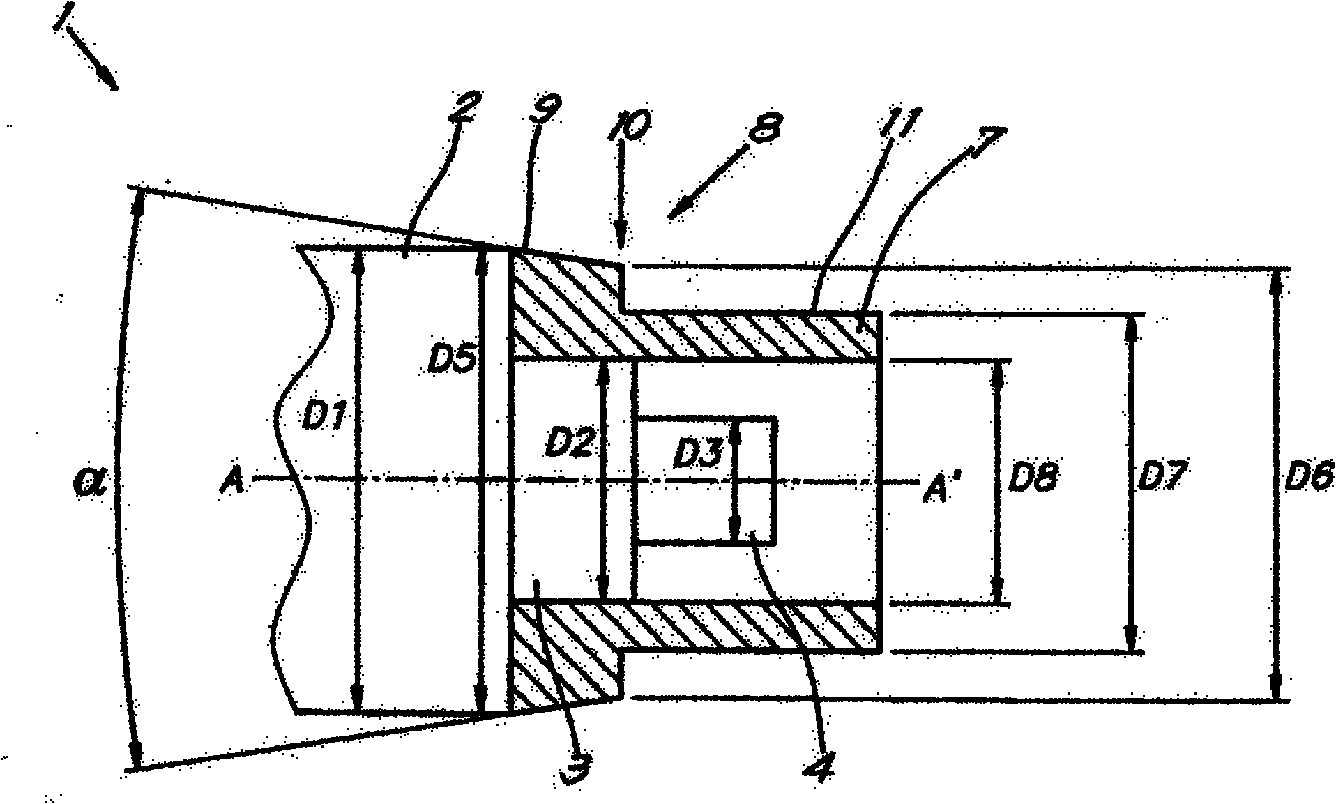
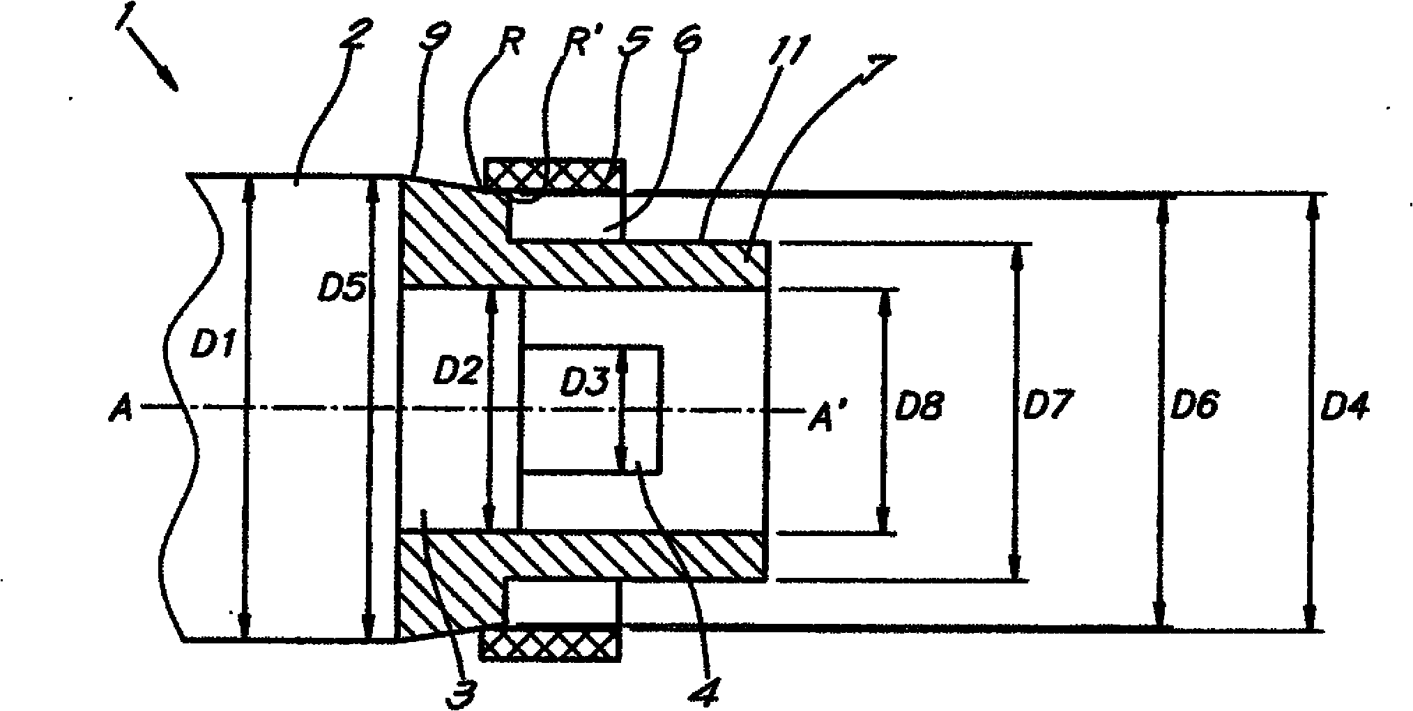
[0063] figure 1 denotes a portion of one distal end of a stepped cylindrical shaft 1, and in this case according to the reduced shaft thickness here, the shaft 1 amounts to at least three cylindrical portions 2, 3 and 4, whereby each of the shaft 1 Sections 2 to 4 have their own diameters, ie from largest to smallest respective diameters D1 , D2 and D3 .

[0064] Such a shaft 1 is only an example of a shaft involved in the method according to the invention, and it may for example be a rotor shaft of a generator, on which permanent magnets are provided and on which a bushing must be provided to Protection such as magnets.

[0065] In another application, the shaft 1 must be, for example, the shaft of an engine, on which a flywheel is provided in order to allow a more stable operation of the motor shaft.

[0066] Of course, many other uses are not exc...


PUM


Abstract

Method for mounting a bush round a part (2) of a shaft with a force fit, which method comprises the following steps: - providing a guide element (7,23) with an outer surface (8) which is at least partly conical; - providing the guide element (7,23) in the extension of the aforesaid part (2) of the shaft (1);- pushing the bush (5) over the guide element (7,23) on the part (2) of the shaft (1).

Description

technical field [0001] The present invention relates to a method of installing a bushing on a portion of a shaft using an interference fit. [0002] Without being limited to the following, the field of application of the invention may be, for example, the mounting of bushings on rotor shafts with permanent magnets of electric machines, or any other application, whereby the bushings must be fixed in a non-rotating manner On a part of the shaft, and thus the bushing, is subjected to rotational forces, for example as is often the case in applications with high rotational speeds. Background technique [0003] Methods for fixing elements on cylindrical parts of shafts are known. [0004] In many cases, as described for example in US4549341, elements are used which have an internal channel with an inner diameter which is smaller than the outer diameter of a part of the shaft mentioned above. [0005] In order to be able to apply such elements on the cylindrical part of the shaft...

Claims


Application Information

Patent Timeline
Patent Type & Authority Applications(China)
IPC IPC(8): H02K15/03B23P19/02
CPCA46B5/00F16C23/00F16D2300/12F16C33/08F16C33/04H02K7/003F16D1/0858B23P11/00B23P19/02F16C35/063H02K15/03Y10T29/53143Y10T29/49895Y10T29/49012Y10T29/49945
Inventor A·普尔尼科夫
Owner ATLAS COPCO AIRPOWER NV
Learn More