Electro-hydraulic control system for working surface hydraulic support

An electro-hydraulic control system and hydraulic support technology, which is applied in mine roof support, mining equipment, earth square drilling and mining, etc., to achieve the effects of cost reduction, novel layout, and convenient memory and operation

Inactive Publication Date: 2011-05-25
BEIJING ZHONGKE LINZHONG TECH
View PDF7 Cites 46 Cited by
  • Summary
  • Abstract
  • Description
  • Claims
  • Application Information

AI Technical Summary

Benefits of technology

The technical effect of this patented technology is improved overall machine performance by providing full functionality with separate human/computer interfaces (Human Machine Interface) boxes instead of just one unit like traditional systems. This makes it easier to maintain and replacements damaged or worn out HMI's on machines due to their limited lifespan. Additionally, there are new designs where connections between different devices have been simplified because they don’t require extra hardware such as connectors or insulation layers. Overall, these improvements improve efficiency and productivity while reducing costs associated with current methods used in machinery operations.

Problems solved by technology

This patented technical problem addressed during the study described earlier describes how long ago it took me months before we could start importing all types of electrical controls that were already available on some companies' equipment manufacturers or suppliers. Existing hydrauled support elecrosis technologies such as electricity hoses and pumps led to slow down progress because they lacked sufficient power supply. Therefore, advanced electronically controlled hydrostatic (EH) controller solutions became popular due to its superior functionality over older methods like mechanical linkage.

Method used


Image

  • Electro-hydraulic control system for working surface hydraulic support
  • Electro-hydraulic control system for working surface hydraulic support
  • Electro-hydraulic control system for working surface hydraulic support

Examples


Embodiment Construction

[0044] The present invention will be explained in detail below in conjunction with the drawings.

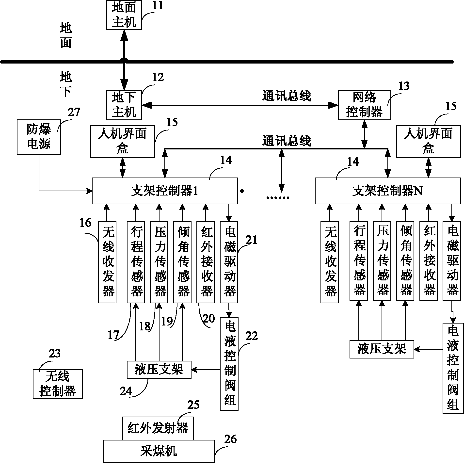
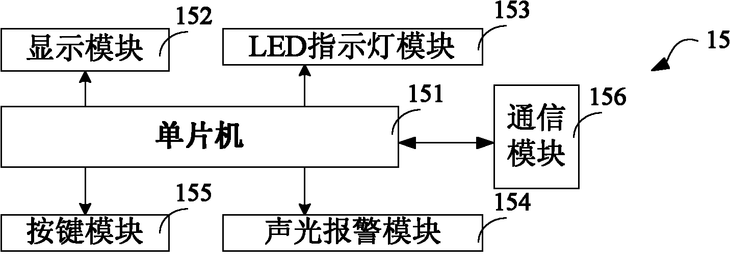
[0045] Such as figure 1 Shows the electro-hydraulic control system of the working face hydraulic support of the present invention, including a ground host 11, an underground host 12, a network controller 13, and at least one support controller 14 connected through a communication bus, and a man-machine interface connected to the support controller 14 Box 15, wireless transceiver 16, stroke sensor 17, pressure sensor 18, tilt sensor 19, infrared receiver 20 and electromagnetic driver 21, and electro-hydraulic control valve group 22 connected to electromagnetic driver 21. The wireless transceiver 16 communicates with the wireless controller in a wireless manner, including downloading an updated program area through wireless communication to update the program in the cradle controller 14. The stroke sensor 17, the pressure sensor 18, the inclination sensor 19 and the electro-hydraulic ...


PUM


Abstract

The invention relates to an electro-hydraulic control system for a working surface hydraulic support. The electro-hydraulic control system comprises a support controller (14), and a control terminal, an information acquisition device and an electromagnetic driver (21) which are connected with the support controller (14), wherein the control terminal is used for inputting an order and displaying received data information, the information acquisition device is used for acquiring the operating parameter data of the hydraulic support, and the electromagnetic driver (21) is used for driving an electro-hydraulic control valve group (22). The electro-hydraulic control valve group (22) connected with the electromagnetic driver (21) is used for controlling the closing and opening of a tube liquid pathway of the hydraulic support. The support controller (14) is used for transmitting the order from the control terminal and supplying the operating parameter data of the hydraulic support acquired by the information acquisition device to the control terminal. The electro-hydraulic control system is applied to the working surface hydraulic support.

Description


Claims


Application Information

Patent Timeline
Owner BEIJING ZHONGKE LINZHONG TECH
Why Eureka
Try Eureka