AI technical title is built by Patsnap AI team. It summarizes the technical point description of the patent document.
A discrimination method and image scaling technology, which are applied in instrumentation, electrical digital data processing, input/output process of data processing, etc., and can solve problems such as image misoperation
Inactive Publication Date: 2011-05-25
GUANGDONG VTRON TECH CO LTD
View PDF3 Cites 11 Cited by
Summary
Abstract
Description
Claims
Application Information
AI Technical Summary
This helps you quickly interpret patents by identifying the three key elements:
Problems solved by technology
Method used
Benefits of technology
Problems solved by technology
[0005] The purpose of the present invention is to solve the problem of image misoperation based on machine vision technology in human-computer interaction, analyze the touch points in the current frame and the initial frame through image analysis technology, and disclose a simple, real-time, and extremely robust Strong image scaling and rotation discrimination methods, so that the machine can understand the real operation that the operator wants to perform, and then perform corresponding actions
Method used
Image
Click on the blue label to locate the original text in one second.
Reading with bidirectional positioning of images and text.
Examples
Embodiment 1
[0067] Such as Figure 2 to Figure 7 As shown, when two touch points on the touch screen are detected, a circular area is generated, and the two touch points in the initial frame are recorded as A 0 (400, 300) and B 0 (600, 300), the circular area formed by it is denoted as S, the center of the circle is denoted as C, and the radius is denoted as R, assuming that relative to A in the Kth frame 0 with B 0 The two touch points are A 1 (300, 150) and B 1 (800, 400).
[0068] Step 1: Judgment A 1 , B 1 Whether there is any point in S, the judgment method is to find the centers C and A respectively 1 , B 1 Euclidean distance between judged Execute step 2;
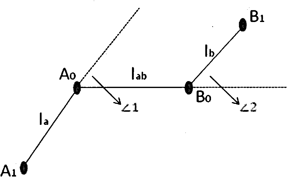
[0069] Step 2: Remember connection A 0 、A 1 The straight line is l a , remember to connect B 0 , B 1 The straight line is l b , respectively draw a straight line l through C a with l b The perpendicular lines intersect at l a The extension line point P a (430, 346) and l b The extension line point P b ...
Embodiment 2
[0075] When two touch points on the touch screen are detected, a circular area is generated, and the two touch points in the initial frame are recorded as A 0 (400, 300) and B 0 (600, 300), the circular area formed by it is denoted as S, the center of the circle is denoted as C, and the radius is denoted as R, assuming that relative to A in the Kth frame 0 with B 0 The two touch points are A 1 (600, 150) and B 1 (450,500).
[0076] Step 1: Judgment A 1 , B 1 Whether there is any point in S, the judgment method is to find the centers C and A respectively 1 , B 1 Euclidean distance between judged Execute step 2;
[0077] Step 2: Remember connection A 0 、A 1 The straight line is l a , remember to connect B 0 , B 1 The straight line is l b , respectively draw a straight line l through C a with l b The vertical line, respectively intersect l a at point P a (564, 348), cross l b at point P b (464, 252), execute step 3;
[0078] Step 3: According to A 0 、A...
PUM
Abstract
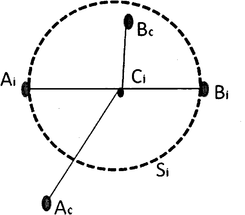
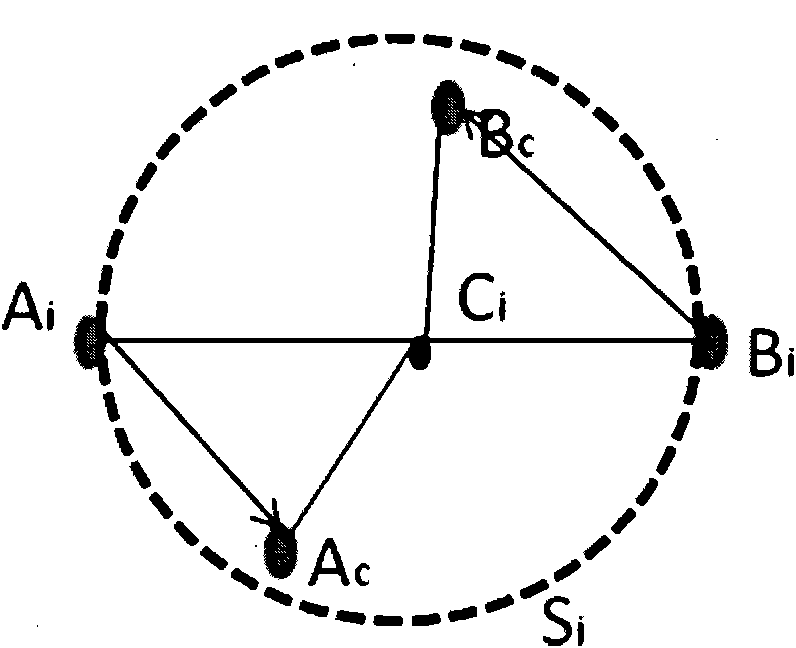
The invention discloses an image zooming and rotating judgment method which comprises the following steps of: initializing an image acquirer, obtaining an initial frame and a current frame, and ensuring positions of each corresponding touch point; setting two touch points in the initial frame to be Ai and Bi, when the touch point which corresponds to the Ai in the current frame is Ac, the touch point which corresponds to the Bi is Bc, remarking a connecting wire between the Ai and the Ac to be 1a, and remarking a connecting wire between the Bi and the Bc to be 1b; forming a circular region Siby taking a connecting wire between the Ai and the Bi as the diameter, remarking the center of the Si as Ci, the semidiameter as R, and judging the position relationship among the Ac, the Bc and the Si; judging to be a rotating operation if only one of the touch points Ac and Bc is positioned in the Si; respectively making the vertical lines of the straight lines 1a and 1b by the centre Ci of a circle if any one of the touch points Ac and the Bc is not positioned in the Si; making a rectangle Ra by taking the Ai and the Ac as a diagonal line; making a rectangle Rb by taking the Bi and the Bc as a diagonal line; and judging whether the Pa and the Pb are positioned in the Ra and the Rb, and judging to be the rotating operation if any one of the points is positioned in the corresponding rectangle otherwise to be a zooming operation. The method is simple and convenient to operate, and high in instantaneity and robustness.
Description
technical field [0001] The invention relates to the fields of image analysis, machine vision and pattern recognition, in particular to a multi-touch image scaling and rotation discrimination method. Background technique [0002] With the development of machine intelligence, people require more natural interaction with machines, and a more direct bridge between the real analog world and the virtual digital world. The multi-touch technology based on machine vision has been vigorously developed in academic research and industrial practice due to its advantages of natural expression and real-time performance. Products based on single touch points have been commercialized, but products based on multi-touch technology have been difficult to commercialize due to various difficulties. The difficulties are mainly based on two aspects: one is technical difficulties; although pattern recognition and machine vision have made great progress in these years, machines still cannot make cor...
Claims
Application Information
Patent Timeline
Application Date:The date an application was filed.
Publication Date:The date a patent or application was officially published.
First Publication Date:The earliest publication date of a patent with the same application number.
Issue Date:Publication date of the patent grant document.
PCT Entry Date:The Entry date of PCT National Phase.
Estimated Expiry Date:The statutory expiry date of a patent right according to the Patent Law, and it is the longest term of protection that the patent right can achieve without the termination of the patent right due to other reasons(Term extension factor has been taken into account ).
Invalid Date:Actual expiry date is based on effective date or publication date of legal transaction data of invalid patent.

