
Permanent-magnetic speed regulation driving system

A drive system, permanent magnet speed regulation technology, applied in the field of drives, can solve the problems of small torque, large size of the corresponding coupler, affecting communication, etc., to reduce the error between shafts, eliminate rigid connections, and large alignment errors Effect

Inactive Publication Date: 2011-05-25
ANSHAN QINYUAN ENERGY SAVING EQUIP MFG
View PDF1 Cites 19 Cited by
  • Summary
  • Abstract
  • Description
  • Claims
  • Application Information

AI Technical Summary

Problems solved by technology

The disadvantages of this type of coupler are: there is only bottom surface magnetic coupling between the magnetic rotor and the conductor rotor, the transmitted torque is small, and the corresponding coupler is large in size, which is not suitable for narrow and long working spaces; the two magnetic rotors move axially The distance must be equal at all times, which increases the design difficulty and makes the system design more complicated
At present, frequency conversion and speed regulation are widely used in industrial sites. Controlling the output speed by controlling the motor is relatively expensive, and the structure and operation are complicated. The power electronic devices of the frequency converter work in the switch state, thus generating a large number of harmonics to pollute the power grid and affect communication. And the requirements for the environment are high, not suitable for working in harsh environments

Method used


Image

  • Permanent-magnetic speed regulation driving system
  • Permanent-magnetic speed regulation driving system
  • Permanent-magnetic speed regulation driving system

Examples


Embodiment 1

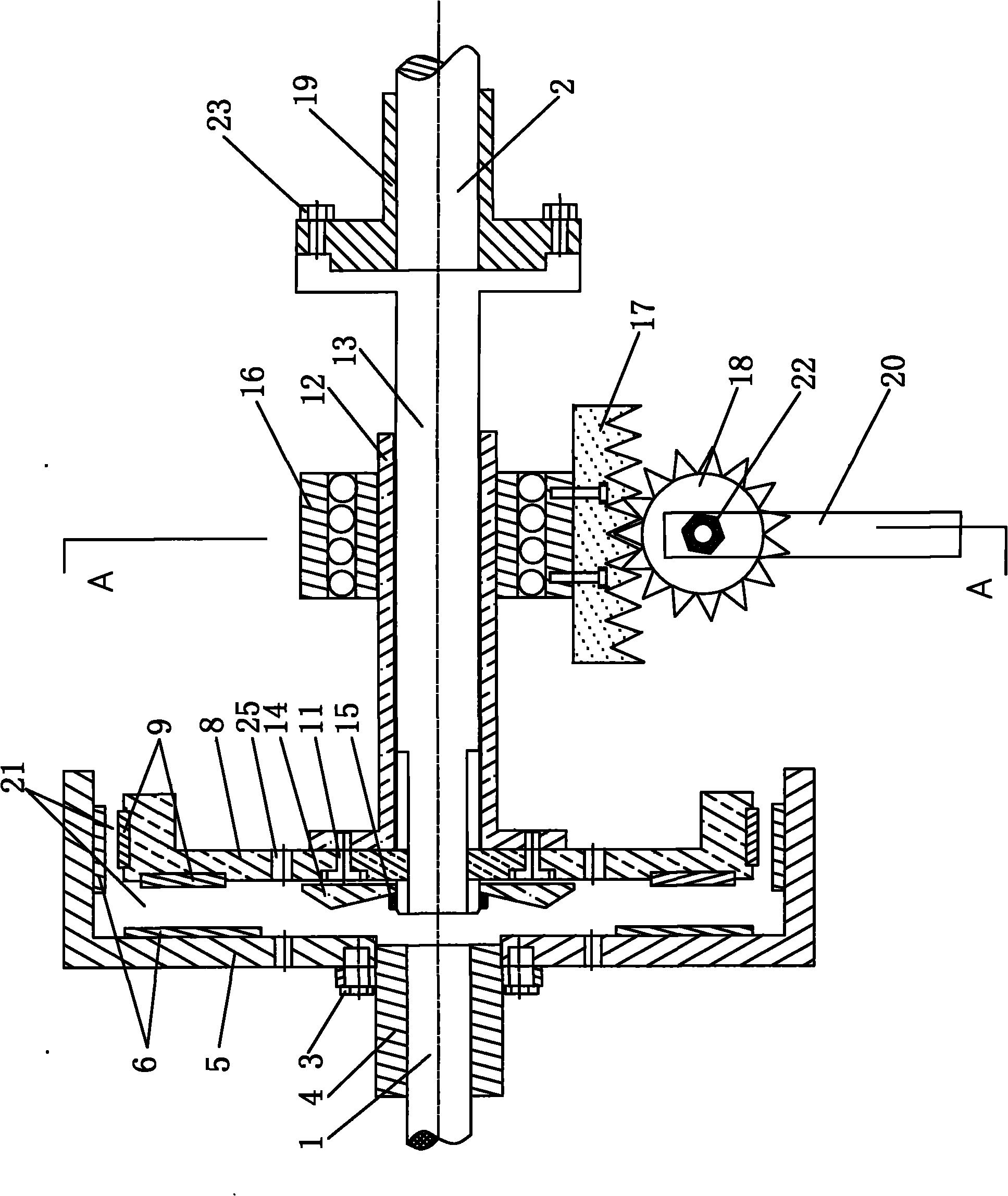
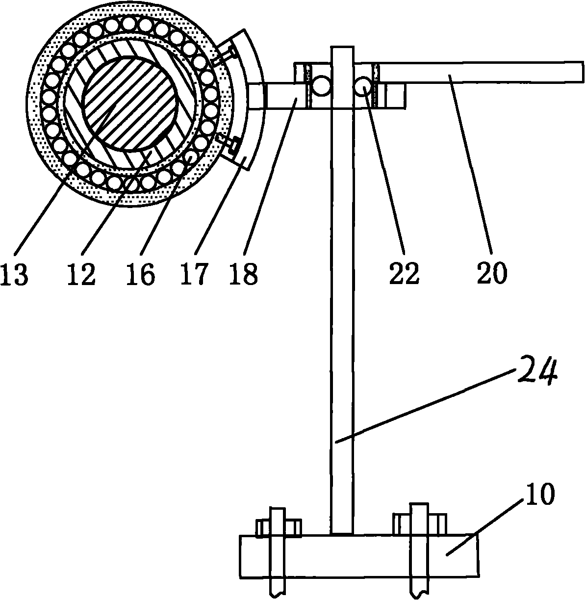
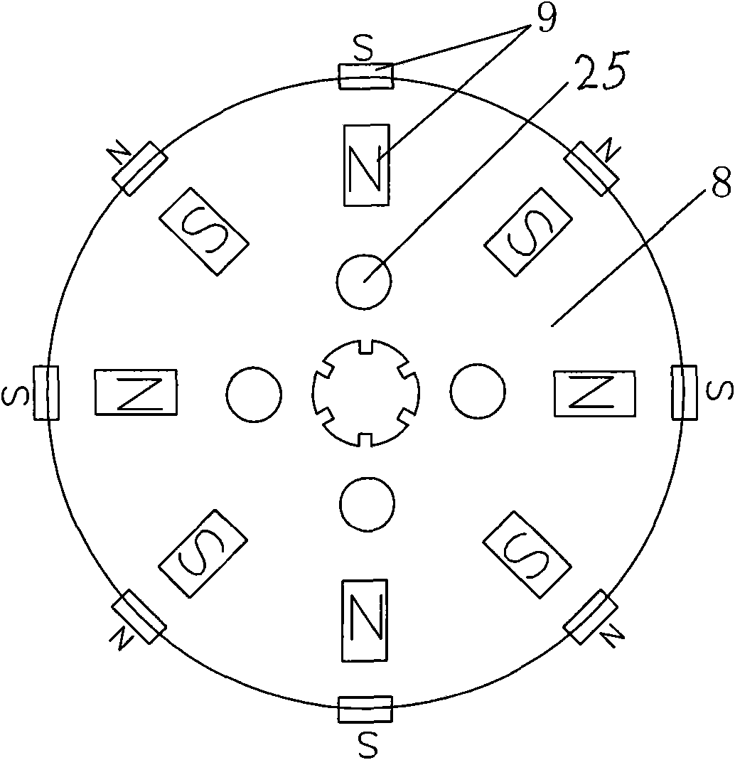
[0017] Embodiment 1: as figure 1 As shown, the present invention includes an input shaft 1 concentrically arranged, a transmission shaft 13, an output shaft 2 connected to the transmission shaft 13, a conductor rotor 5 installed at the end of the input shaft 1, and a conductor rotor 5 that is slidably installed at the end of the transmission shaft 13 and extends into the conductor rotor. The permanent magnet rotor 8 in 5 and the speed regulating device installed on the transmission shaft 13 and connected with the permanent magnet rotor 8, the other end of the speed regulating device is fixed on the base 10, the conductor surface of the conductor rotor 5 and the permanent magnet rotor 8 The magnetic pole faces are arranged correspondingly, and an air gap 21 is formed therebetween. The conductor rotor 5 is connected and fixed by the shaft sleeve 4 and the first bolt 3 , and the output shaft 2 and the transmission shaft 13 are connected and fixed by the fixing sleeve 19 and the s...


PUM


Abstract

The invention discloses a permanent-magnetic speed regulation driving system, and belongs to the technical field of drivers. The system comprises an input shaft and a transmission shaft arranged concentrically, an output shaft connected with the transmission shaft, a conductor rotor arranged at the end of the input shaft, a permanent-magnetic rotor glidingly arranged at the end of the transmission shaft and extending into the conductor rotor, and a speed regulation device arranged on the transmission shaft and connected with the permanent-magnetic rotor, wherein the other end of the speed regulation device is fixed on a base; and the conductor surface of the conductor rotor is arranged corresponding to the pole surface of the permanent-magnetic rotor, and an air clearance is formed between the conductor surface and the pole surface. The shafts are arranged concentrically, the two rotors are separated through the air clearance, and the two shafts have no any direct mechanical connection by coupling of magnetic field effect, so rigid connection between a motor shaft and a load shaft is eliminated, vibration isolation between a load and a motor is not mutually affected, and a bigger centering error is allowed; and when the equipment is overload, the equipment can also be protected, and soft starting function is provided. The system not only can avoid the generation of harmonic, but also has strong adaptability to a severe environment.

Description

technical field [0001] The application of the present invention belongs to the technical field of drives, and in particular relates to a permanent magnet speed-regulating drive system. Background technique [0002] At present, most of the coupling mechanisms widely used in the industry are rigid connections. Due to the complex and changeable operation of the system, no matter how to ensure the strict alignment of the two axes, the equipment will vibrate after a period of operation, thereby accelerating wear and shortening the life of the equipment. . The existing permanent magnetic coupling structure is an invention patent with the patent number of 98802726.7, which discloses an adjustable magnetic coupler. The specific structure is: two conductor rotors installed on the rotatable shaft, installed on the second rotating Two magnetic rotors on the shaft. The magnetic rotor is located between two conductive rotors and maintains an air gap with the adjacent rotor. The size of...

Claims


Application Information

Patent Timeline
IPC IPC(8): H02K49/10
Inventor 满永奎王大志马忠威边春元王双全
Owner ANSHAN QINYUAN ENERGY SAVING EQUIP MFG
Learn More