Circuit and topology for high-reliability power electronic device system

A power electronic device, reliability technology, applied in the field of circuit and system topology

Inactive Publication Date: 2011-05-25
GENERAL ELECTRIC CO
View PDF4 Cites 10 Cited by
  • Summary
  • Abstract
  • Description
  • Claims
  • Application Information

AI Technical Summary

Problems solved by technology

Passive components require most of the

Method used


Image

  • Circuit and topology for high-reliability power electronic device system
  • Circuit and topology for high-reliability power electronic device system
  • Circuit and topology for high-reliability power electronic device system

Examples


Embodiment Construction

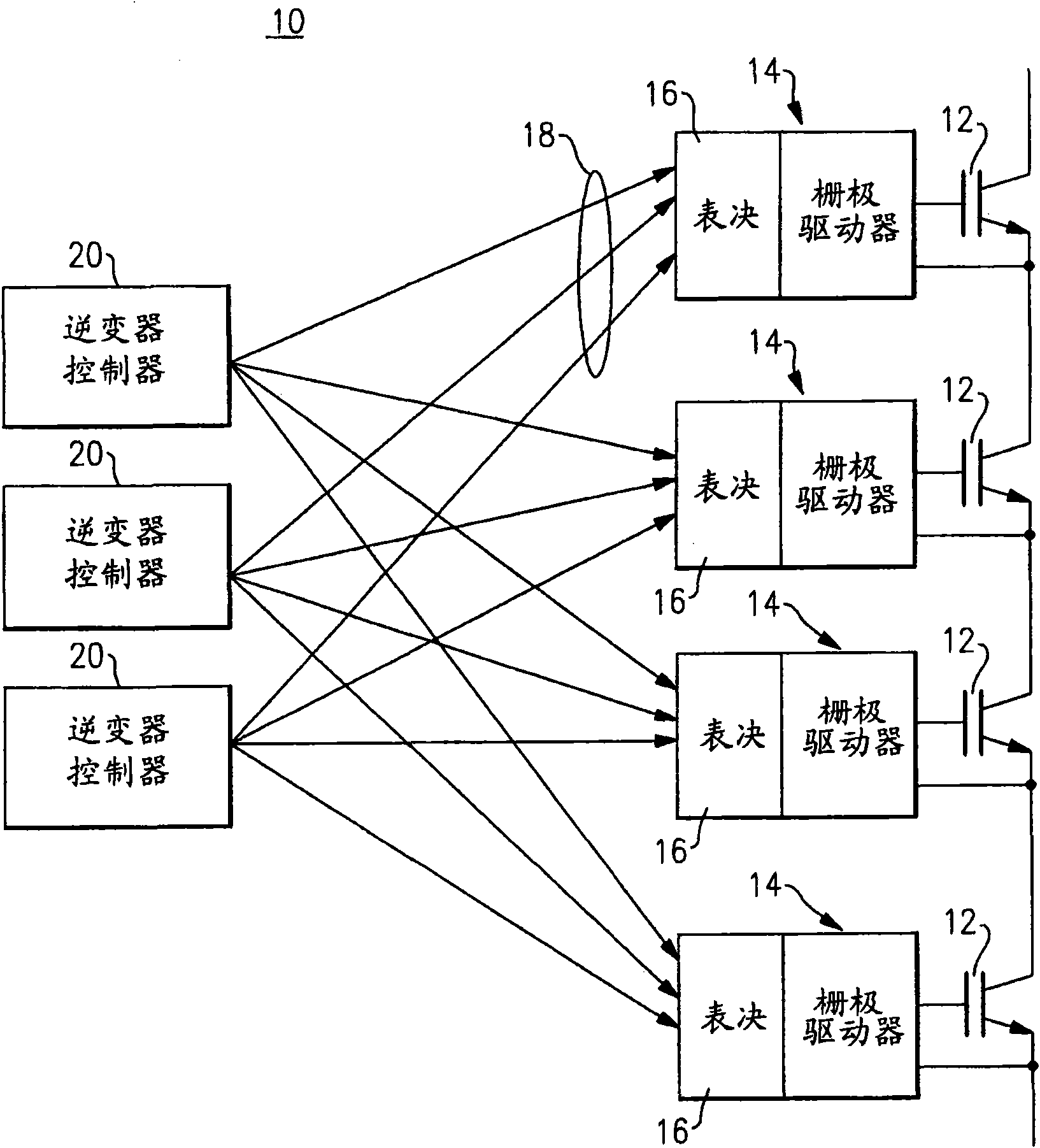
[0029] figure 1 Circuit and system topologies are shown for a power electronics system without a single point of failure, which serves as a fundamental building block for many different implementations. The high power electronics system 10 functions as a single switch and can be used in nearly every known power electronics topology. It comprises a plurality (n+1) of substantially identical bulk power switchgear 12 such as, but not limited to, power semiconductors connected in a series configuration to provide a desired level of switching redundancy such that the switchgear After one or more of the 12 short-circuit failure modes occur, the switch can still continue to operate. The power semiconductors can be IGBTs or IGCTs or thyristor devices, but are not limited thereto.

[0030] By extending the foregoing redundancy features throughout the system, the power electronics system 10 provides a desired level of reliability / availability. While a standard gate drive unit has onl...


PUM


Abstract

The invention relates to a circuit and topology for a high-reliability power electronic device system. The circuit and system topology comprising a plurality of controller units (20) is configured into a power system (10) providing high reliability. The controller units (20) control a subsystem and equipment so that the high-reliability power system (10) can also maintain running after the controller units (20), the subsystems (14) and (16) and the equipment (12) have failure.

Description

technical field [0001] The present invention relates generally to power electronics and, more particularly, to circuits and system topologies that provide high reliability power systems. Background technique [0002] Power electronics systems in the megawatt range usually consist of a large number of power and control elements. Redundancy concepts, in addition to making components durable, are often used to increase the reliability of the power electronics system. One of the most common examples of redundant topologies is that n+1 or more elements such as thyristors are connected in series. This series technique generally limits the redundancy of the power semiconductors (power semiconductors), as does the control system itself, especially the interface between the control system and the power semiconductor(s) is not redundant. [0003] The risk of failure of a non-redundant interface between the control system and the power semiconductors, which is acceptable for standard...

Claims


Application Information

Patent Timeline
IPC IPC(8): H02M1/08
Inventor C・M・西勒R・勒斯纳
Owner GENERAL ELECTRIC CO
Why Eureka
Try Eureka