
Vacuum suction device for frame and operation method thereof

A plate frame and vacuum technology, which is applied in the field of vacuum clamping devices for plate frames, can solve the problems of uneven pressure, reduced work efficiency, uneven pressure, etc. Effect

Inactive Publication Date: 2011-06-01
MASTERWORK GROUP CO LTD
View PDF8 Cites 0 Cited by
  • Summary
  • Abstract
  • Description
  • Claims
  • Application Information

AI Technical Summary

Problems solved by technology

When processing large-format printed products, because the corresponding frame is also relatively large, the middle area of ​​the frame often deforms and collapses, so that the frame and the platform cannot be completely adhered, resulting in uneven pressure during die-cutting and die-cutting. The cutting accuracy is reduced and the work efficiency is reduced
[0003] In order to solve this problem, in the existing large-format equipment, one method is to embed an electromagnet in the middle of the platform, and the corresponding plate frame must be made of a material that can be magnetized, and the plate frame and the platform are tightly attached by magnetic force. However, this method has high requirements on the magnetic force of the electromagnet, and it is difficult to select materials; another method is: open a groove in the middle of the platform, use mechanical embedding, and lock the plate frame to make the plate frame and the platform It fits tightly, but due to the groove in the middle of the platform, there will still be uneven pressure during die-cutting, and the installation and adjustment are also complicated

Method used


Image

  • Vacuum suction device for frame and operation method thereof
  • Vacuum suction device for frame and operation method thereof
  • Vacuum suction device for frame and operation method thereof

Examples


Embodiment

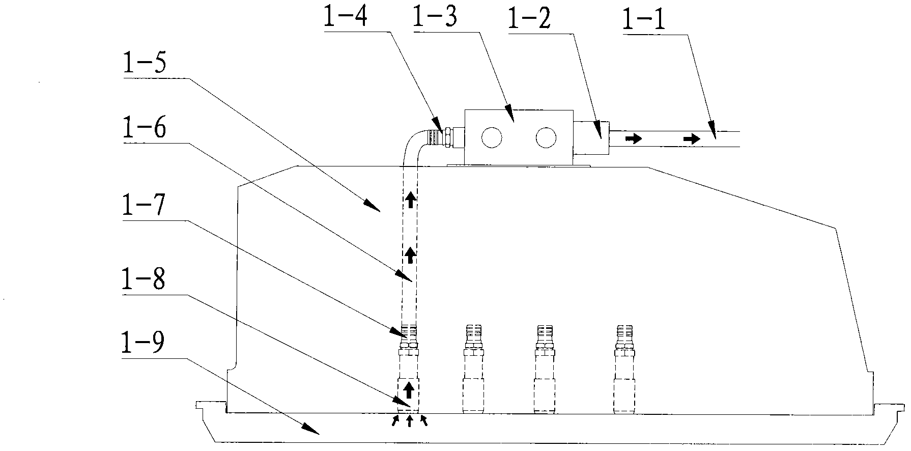
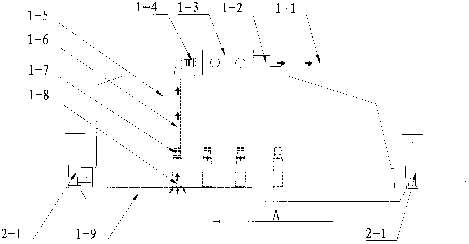
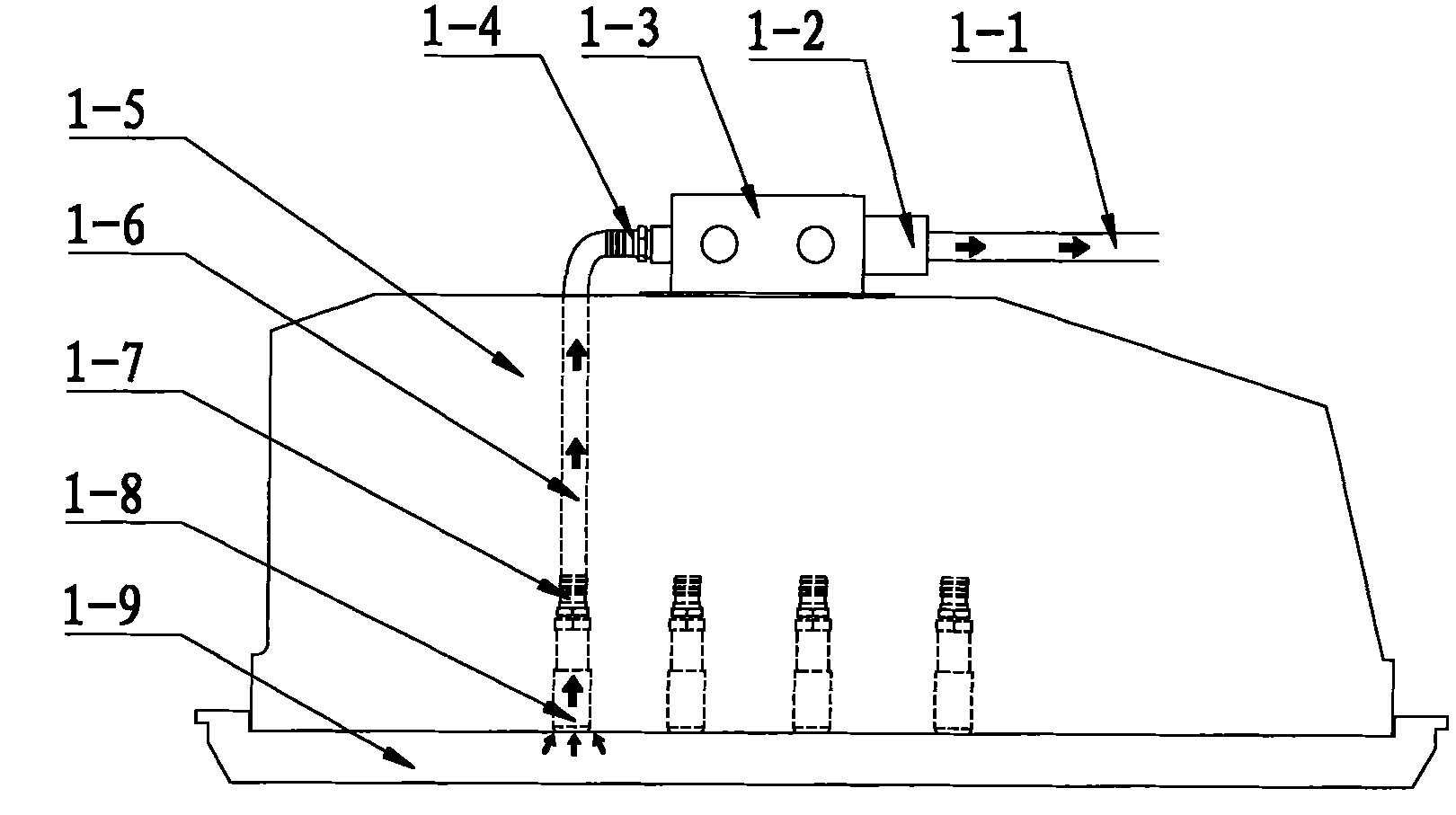
[0023] Example: A vacuum suction device for the plate frame (see figure 1 , figure 2 ), which is characterized in that it includes the main airway suction pipe 1-1, the platform 1-5, the branch airway pipe 1-6, the branch airway pipe joint 1-7, the suction nozzle 1-8 and the frame 1- 9; The suction nozzle 1-8 is fixedly installed in the platform 1-5 according to the thread and is perpendicular to the frame 1-9, and the end surface of the suction nozzle 1-8 is on the same plane as the lower plane of the platform 1-5 Plane, the other end of the suction nozzle 1-8 is connected with the branch pipe joint 1-7 according to the thread; one end of the branch suction pipe 1-6 is connected with the branch pipe joint 1-7, and the other One end is connected with one end of the main air suction pipe 1-1; the other end of the main air suction pipe 1-1 is connected with the vacuum generator; the middle area of ​​the frame 1-9 has a certain deformation and Collapse.

[0024] A gas path instal...


PUM


Abstract

The invention relates to a vacuum suction device for a frame, which comprises a main air-path air-suction pipe, a platform, a branch air-path pipe, a branch air-path pipe tie-in, a vacuum nozzle and a frame. An operation method thereof comprises the following steps: starting a vacuum generator and sucking airflow from the vacuum nozzle; forming vacuum between the lower plane of the platform and the upper plane of the frame, tightly sucking a middle deformed and sunken area of the frame on the platform, and completely fitting two planes together; stopping the vacuum generator, stopping the vacuum nozzle sucking air, ensuring no airflow flows in the branch air-path pipe and the main air-path air-suction pipe, and recovering to a constant pressure state; and recovering the constant pressure state between the lower plane of the platform and the upper plane of the frame, and keeping a clearance between the middle deformed and sunken area of the frame and the lower plane of the platform. The vacuum suction device for a frame and the operation method thereof have the advantages that the problem of the uneven pressure caused by deformed and sunken frame is solved, the die cutting precision is increased, the applicability is strong, the device can be applied to the frame made of various materials, the structure is simple and the operation is convenient.

Description

(1) Technical field: [0001] The invention is suitable for printing machinery, and is especially suitable for a vacuum suction device for plate frame installation and its working method, namely a vacuum suction device for plate frame and its working method. (2) Background technology: [0002] With the rapid development of the printing industry, the types of printed products continue to increase, and the demand for equipment for processing large-format printed products is also increasing. When processing large-format prints, due to the large size of the corresponding plate frame, the middle area of ​​the plate frame often deforms and collapses, which makes the plate frame and the platform unable to be completely adhered to each other, resulting in uneven pressure during die cutting. Cutting accuracy is reduced and work efficiency is reduced. [0003] To solve this problem, one method in the existing large-format equipment is to embed an electromagnet in the middle of the platform, a...

Claims


Application Information

Patent Timeline
Patent Type & Authority Applications(China)
IPC IPC(8): B26D7/26B41F13/56
Inventor 首云飞
Owner MASTERWORK GROUP CO LTD
Learn More