
Jet injector with variable nozzle position

A technology of jet pump and nozzle, applied in the field of jet pump, can solve the problem of waste of manpower and material resources, and achieve the effects of easy realization, simple production and disassembly, and simple structure

Inactive Publication Date: 2011-06-01
HENAN POLYTECHNIC UNIV
View PDF7 Cites 5 Cited by
  • Summary
  • Abstract
  • Description
  • Claims
  • Application Information

AI Technical Summary

Problems solved by technology

In order to test the impact of nozzles in different positions on the performance of jet pumps, jet pumps of different shapes are required in actual tests, resulting in waste of manpower and material resources. Therefore, we need a jet pump that can flexibly change the position of the nozzles. The purpose is to solve this problem

Method used


Image

  • Jet injector with variable nozzle position
  • Jet injector with variable nozzle position
  • Jet injector with variable nozzle position

Examples


Embodiment Construction

[0013] In order to make the purpose, technical solution and advantages of the present invention clearer, the present invention will be further described in detail below in conjunction with the accompanying drawings and specific embodiments.

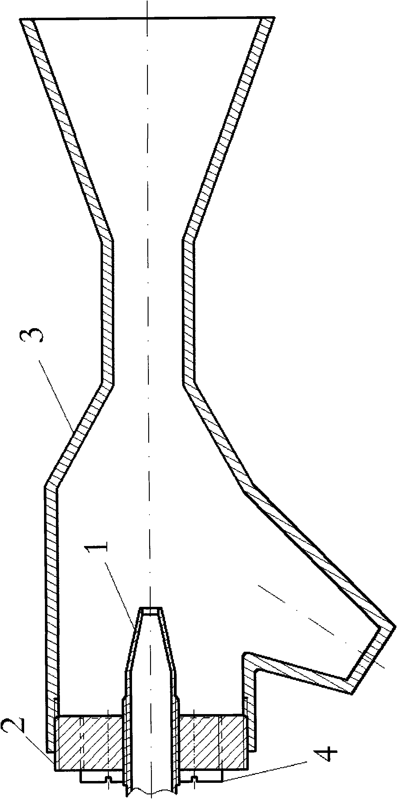
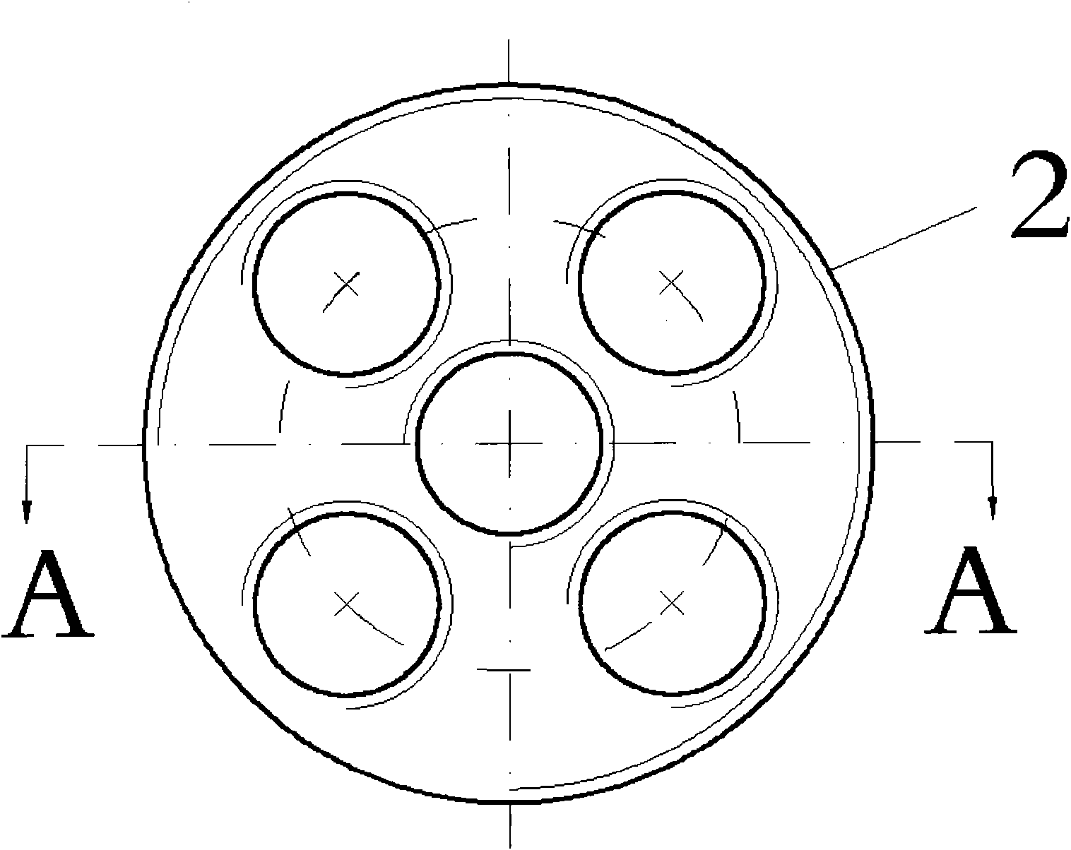
[0014] figure 1 It is a structural schematic diagram of the jet pump of the present invention. Such as figure 1 As shown, a jet pump with variable nozzle position according to the present invention has four structures: nozzle (1), side cover (2), pump body (3) and threaded cylindrical pin (4), wherein The side cover (2) and the pump body (3) are connected through a threaded part, and the nozzle (1) and the threaded cylindrical pin (4) are connected with the threaded through hole in the side cover (2) through an external thread structure.

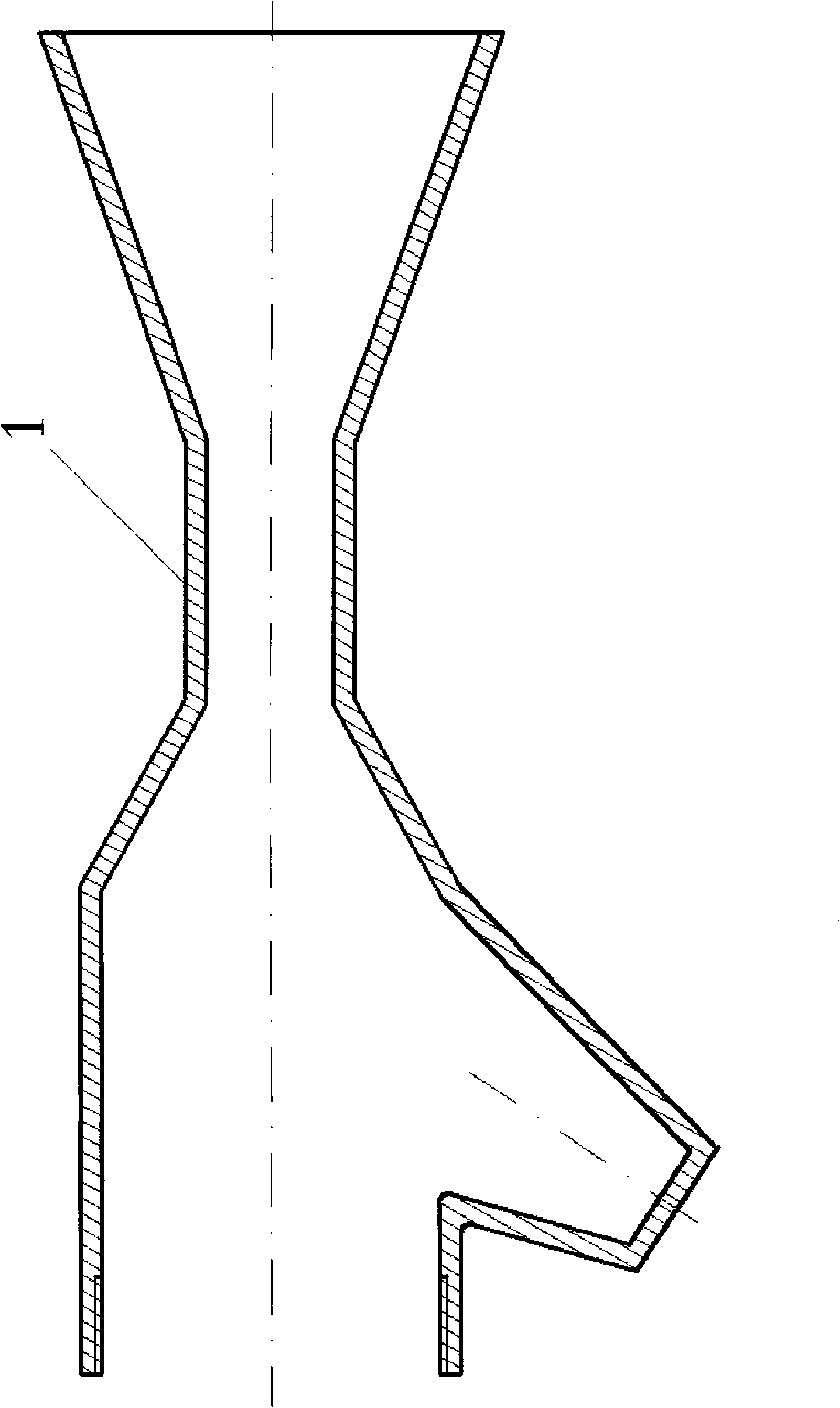
[0015] figure 2 It is a schematic diagram of the pump body structure of the jet pump of the present invention. Such as figure 2 As shown, the pump body (3) has a threaded hole structure at one en...


PUM


Abstract

The invention provides a jet injector with variable nozzle position. The currently applied jet injector has fixed structure, and the nozzle position is constant in the jet injector, but the jet injector always has an asymmetric shape so that the influence of nozzles in different positions on the jet injector performance is needed to research, and jet injectors in different shapes are needed in practical tests to cause labor and material waste. The jet injector provided by the invention can randomly changes the nozzle position and adopt the technical scheme that a lateral cover (2) and a pump body (3) are connected together through thread, a nozzle (1) can be connected with any threaded hole on the lateral cover (2), and other threaded holes on the lateral cover (2) are sealed and connected with threaded cylindrical pins (4). By flexibly changing the related connecting position of the lateral cover (2) and the pump body (3) and the connecting position between the nozzle (1) and the threaded hole on the lateral cover (2), the nozzle position in the jet injector is changed, and the experimental aim is achieved.

Description

Technical field: [0001] The invention relates to a jet pump capable of changing the nozzle position, which is used for studying the influence of nozzles at different positions on the performance of the jet pump. Background technique: [0002] The structure of the currently used jet pump is fixed, the position of the nozzle in the jet pump is invariable, and the shape of the jet pump is often asymmetrical, so it is necessary to study the influence of nozzles in different positions on the performance of the jet pump. In order to test the impact of nozzles in different positions on the performance of jet pumps, jet pumps of different shapes are needed in actual tests, resulting in waste of manpower and material resources. Therefore, we need a jet pump that can flexibly change the position of the nozzles. The purpose is to solve this problem. Invention content: [0003] In view of this, the main purpose of the present invention is to change the position of the nozzle in the j...

Claims


Application Information

Patent Timeline
Patent Type & Authority Applications(China)
IPC IPC(8): F04F5/46
Inventor 李同卓毕鹏飞邓珊
Owner HENAN POLYTECHNIC UNIV
Learn More