
Edge blending method for splicing multiple projection images

An edge fusion and projected image technology, applied in image communication, components of color TV, components of TV system, etc., can solve the problems of difficult installation, difficult hardware installation, less calculation, etc., to achieve smooth transition and color. Even, accurate results

Inactive Publication Date: 2011-06-01
苏州创捷传媒展览股份有限公司
View PDF0 Cites 35 Cited by
  • Summary
  • Abstract
  • Description
  • Claims
  • Application Information

AI Technical Summary

Problems solved by technology

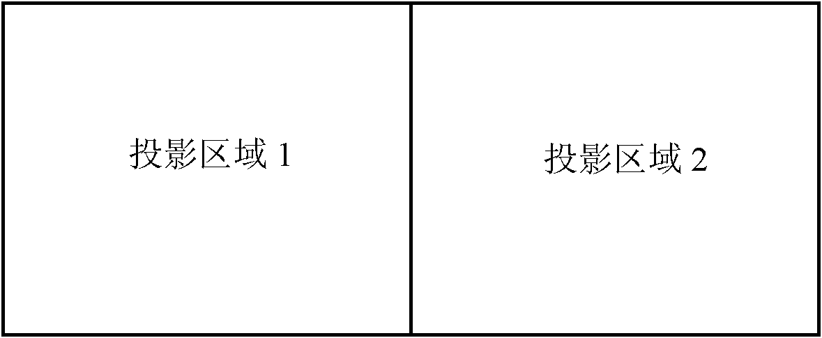
This method is simple to implement and requires less calculation; however, it is difficult to install the hardware, and it is difficult to install it in a seamless state. There will be obvious splicing gaps at the connecting part of the two projectors;
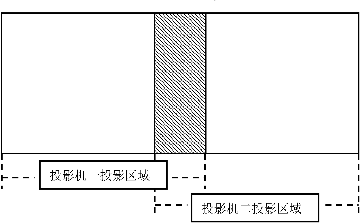
[0006] (2) Simple overlap: that is, the images of the two projectors partially overlap, but there is no attenuation of color and brightness
This method is simple to implement and requires less calculation. Although there will be no gaps in the overlapping parts of the projection area, the superimposed area is obviously brighter than other non-superimposed areas, which affects normal viewing.

Method used


Image

  • Edge blending method for splicing multiple projection images
  • Edge blending method for splicing multiple projection images
  • Edge blending method for splicing multiple projection images

Examples


Embodiment

[0033] Embodiment: a kind of edge blending method that is used for multiple projection image mosaic, as attached Figure 4-5 shown, including the following steps:

[0034] step one. Sets the size of the projected overlap area between adjacent projected images.

[0035] Step two. According to the number of projectors, the resolution and the size value of the projection overlapping area, each frame of image is divided based on pixels, for example: in the horizontal mosaic mode of 3 projectors, if the overlapping area is 256 pixels, the resolution of each projector is 1024*768, then a large-size desktop with a resolution of 2560*768 can be spliced ​​and displayed at most. This step is to divide the 2560*768 size frame image into three overlapping 1024*768 size images. The offsets of these three images relative to the upper left corner of the original image are (0,0), ( 768,0), (1536,0).

[0036] Step three. The size of the image overlapping area projected by each projector ...


PUM


Abstract

The invention discloses an edge blending method for splicing multiple projection images, comprising the following steps: setting the size value of a projection overlapping region between adjacent projection images; cutting each frame of image based on pixels according to the number and the resolution of projectors and the size value of the projection overlapping region; setting the sensitivity weights of color channels of red, green and blue of each projector; calculating the boundary distance from each pixel point in each image to the boundary of the image; according to the boundary distance and the size value of the projection overlapping region, calculating the color weight of each pixel point; according to the sensitivity weights of the color channels and the color weight of the pixel point, calculating to obtain the pixel attenuation weight vector of the projection overlapping region; and respectively multiplying the red color value, the green color value and the blue color value of each pixel point in the image overlapping region by the respective pixel attenuation weight vector. The edge blending method overcomes the image overlapping region display defects in the existing multi-projector projection technology, and realizes that images from multiple projectors form smooth transition in the overlapping region, thereby greatly improving the whole visual effect of a picture.

Description

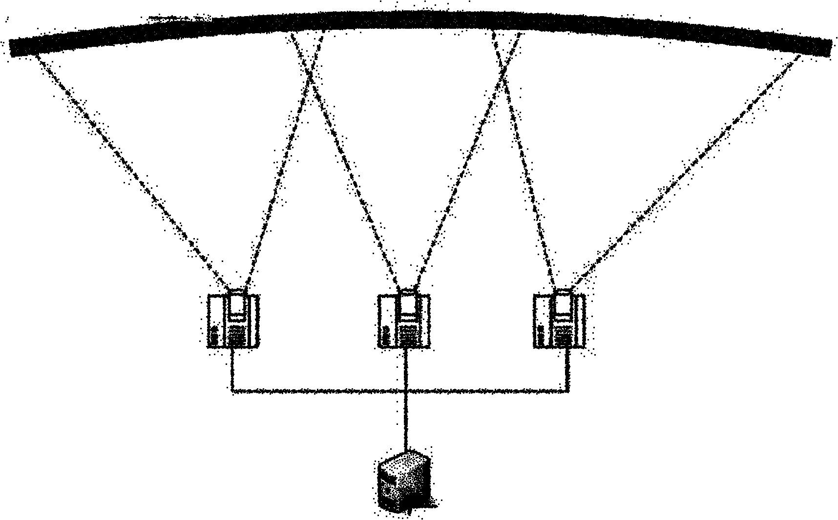
technical field [0001] The invention relates to a projector image display method, in particular to an edge fusion method for splicing multiple projection images. Background technique [0002] High-resolution, high-brightness large-screen displays are more and more widely used in scientific computing visualization, industrial design, virtual manufacturing, military simulation, entertainment and other fields. Currently widely used large-screen display systems either use large-screen display walls or high-performance projectors, which are very expensive. Therefore, a high-resolution large-screen display system that uses multiple projector arrays for seamless splicing is becoming more and more popular. [0003] The system structure diagram of multi-projector mosaic display is as follows: Figure 1-2 As shown, the splicing of the projector array composed of multiple projectors can realize the display of the screen, and the seamless splicing of the projection array composed of fo...

Claims


Application Information

Patent Timeline
IPC IPC(8): G03B21/00H04N5/74G06F3/14
Inventor 毛小松孟庆涛
Owner 苏州创捷传媒展览股份有限公司
Learn More