Safe broadcasting monitoring system based on video/audio matching technology

A technology for safe broadcasting and monitoring systems, which is applied to televisions, instruments, electrical components, etc. It can solve the problems of excessive difference between the left and right channels of audio signals, affecting the final broadcasting quality, and failing to meet the safety broadcasting requirements. The effect of stress, expanding the scope of monitoring, and avoiding broadcast accidents

Active Publication Date: 2011-06-01
BEIJING DAYANG TECH DEV
View PDF3 Cites 22 Cited by
  • Summary
  • Abstract
  • Description
  • Claims
  • Application Information

AI Technical Summary

Problems solved by technology

If the staff is slightly negligent and does not find any abnormalities in the final broadcast signal, it will lead to broadcast accidents such as black frames and still frames in the final broadcast screen
Moreover, in such a situation where the spirit is in a state of tension for a long time, even if the abnormality of the last-stage broadcast signal can be found in time, it is easy to cause human misoperation accidents during emergency handling of the broadcast control
In addition, for the final broadcast signal of the channel sub-control system, if some technical indicators of the signal have problems, such as the difference between the left and right channels of the audio signal is too large, the phase is reversed, and the video signal continues to freeze for a period of time, similar to this signal abnormality The situation cannot be found through manual subjective judgment at all, it will inevitably affect the quality of the final broadcast, and cannot meet the requirements of safe broadcast

Method used


Image

  • Safe broadcasting monitoring system based on video/audio matching technology
  • Safe broadcasting monitoring system based on video/audio matching technology
  • Safe broadcasting monitoring system based on video/audio matching technology

Examples


Embodiment 1

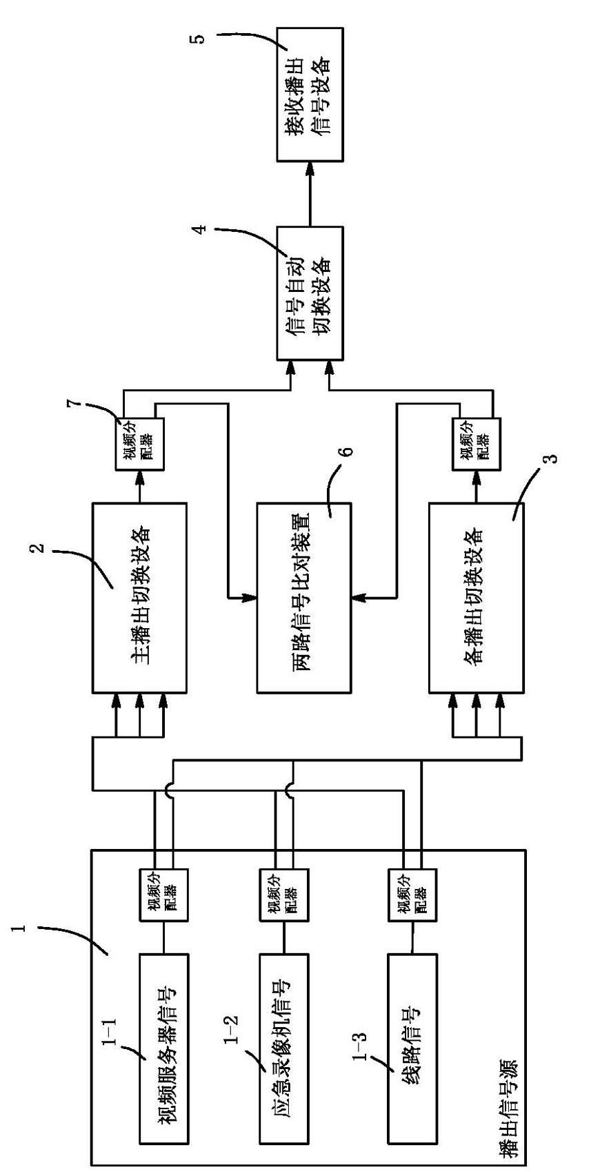
[0027] An embodiment of a safe broadcast monitoring system based on video and audio comparison, see figure 1 and figure 2 , the safe broadcast monitoring system includes: a device 1 for providing a broadcast signal source, and the broadcast signal source device includes: a video server 1-1 providing most of the program signals, a video recorder 1-2 providing emergency signals, And the line signal 1-3 that provides live broadcasting or rebroadcasting; Be connected with this equipment and be used for broadcasting the main broadcasting switching equipment 2 of signal; This equipment is also connected with the standby broadcasting switching equipment 3 that is used for broadcasting signal; The rear of the standby broadcast switching device is connected with a signal automatic switching device 4 for outputting the main broadcast switching device and the output of the standby broadcast switching device; the back of the signal automatic switching device is connected with a device 5 ...

Embodiment 2

[0040] An embodiment of the second connection mode of the safe play monitoring system based on video and audio comparison, see image 3 And embodiment 1, said two-way signal comparison device is a comparison device for the broadcast signal of the main broadcast switching device and the broadcast signal source, and for the broadcast signal and the broadcast signal source of the standby broadcast switching device comparison device.

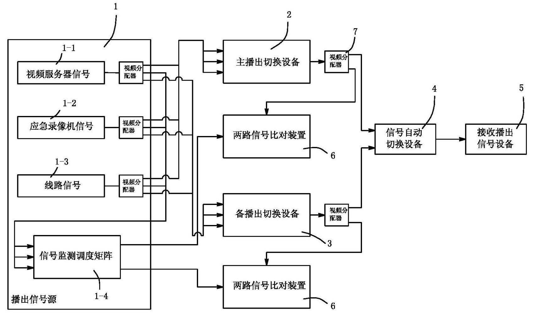
[0041] In addition to the broadcast signal source equipment including: video server, video recorder, and line signal, it is also equipped with a signal monitoring and dispatching matrix 1-4 for safe broadcast monitoring. The above broadcast signal sources are respectively sent to the video distributor for video and audio signal distribution. After distribution, each signal source provides 3 channels of signals. Among them, the first signal is connected to the signal input end of the main broadcast switching device according to the signal source seq...

Embodiment 3

[0051]Because digital media is easy to copy and modify without loss, it makes data tampering easier. Moreover, equipment failures in the transmission link will also cause picture damage to varying degrees, loss of chrominance and brightness components, mosaics caused by data block damage during codec and transmission, etc. In order to detect whether the video signal at the receiving end has been maliciously tampered with, it can be judged by comparing the original broadcast signal with the return signal at the receiving end.

[0052] Therefore, this embodiment is the third connection mode of the safe play monitoring system based on video and audio comparison, see Figure 4 As in Embodiment 1, the two-way signal comparison device is a comparison device for the broadcast signal of the automatic switching device and the return signal of the broadcast signal receiving device.

[0053] The main and backup signals of the broadcast channel sub-control system are sent to the back-end...


PUM


Abstract

The invention relates to a safe broadcasting monitoring system based on video/audio matching technology, comprising a device for supplying a broadcasting signal source, a primary broadcasting switch device of signals, a secondary broadcasting switch device of signals, a device for automatically switching the signals outputted by the primary broadcasting switch device and the secondary broadcasting switch and a broadcasting signal receiving device for receiving signals; a two-path signal matching device for matching two paths of signals is connected between any two paths of signal outputs of the devices. The beneficial effects generated by the invention are that the objective analysis for final-stage broadcasting signal audio technology indexes is realized in the sub-control system of the broadcasting channel by introducing the two-path signal matching device; the monitoring range of safe broadcasting is enlarged, and the safe broadcasting is not limited by artificial subjective judgment, so that the safety of the broadcasting system is further developed; automatic discovery, fast warning and in-time process for the abnormity of the broadcasting final-stage signal are realized; broadcasting accidents are effectively avoided; and the safety of broadcasting is improved.

Description

technical field [0001] The invention relates to a safe broadcast monitoring system based on video and audio comparison technology, which is a system for analyzing, comparing and alarming the final signal in the broadcast channel sub-control system under the computer network environment. The safe broadcast monitoring technology of TV station broadcast system. Background technique [0002] Usually, when TV stations design and build broadcast control systems, broadcast security is the primary consideration, and safe broadcast is the ultimate goal of every TV station's broadcast system. For the broadcast sub-control system, the security of the broadcast system can be realized in various ways, such as adopting a redundant backup structure for the core equipment inside the system to avoid a single failure point; optimizing the broadcast by improving the application program The control logic of signal scheduling can improve the control accuracy, and some automatic fault handling m...

Claims


Application Information

Patent Timeline
Patent Type & Authority Applications(China)
IPC IPC(8): H04N17/00H04N17/02G08B21/00
Inventor 姚威商同李智鹏曾国卿郑凯王付生尚秀勇黄一辰
Owner BEIJING DAYANG TECH DEV
Why Eureka
Try Eureka