A wind turbine blade

A technology of wind turbines and blades, applied to wind engines, wind engines consistent with the wind direction, engines, etc., can solve the problems of low manufacturing stability, high part cost, and unallowable manufacturing locations, etc., and achieve the effect of reducing stress

Active Publication Date: 2011-06-01
BLADE DYNAMICS LTD
View PDF11 Cites 3 Cited by
  • Summary
  • Abstract
  • Description
  • Claims
  • Application Information

AI Technical Summary

Problems solved by technology

Also, due to the size of the aerodynamic fairings, it is not possible to transport them over great distances and thus can only be constructed close to the final wind farm location
This does not allow for variety in manufacturing locations and processes which ultimately leads to lower manufacturing stability and higher part cost

Method used


Image

  • A wind turbine blade
  • A wind turbine blade
  • A wind turbine blade

Examples


Embodiment Construction

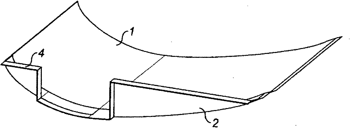
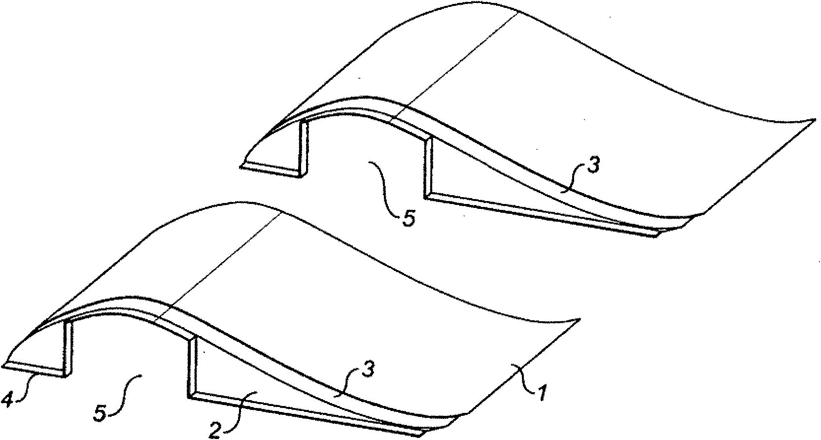
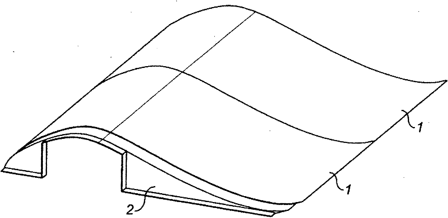
[0027] The skin panel consists of a skin part 1 and a partition 2 . The skin part 1 has an aerodynamic profile shape corresponding to a part of a half wind turbine blade. At the end closest to the tip of the final blade, the skin portion is provided with a recess 3 extending across the entire width of the blade and arranged to support an adjacent wall plate. The partitions 2 are positioned at the same end and extend across the entire width of the inner surface of the skin portion. A flange 4 extends across the inner surface of the bulkhead providing a contact surface. The flange 4 is provided with an opening 5 which fits around the spar described below.

[0028] Leading and trailing edge joints at Figure 4 , 4A and 4B are shown. Upper skin panel 10 and lower skin panel 11 are in as Figure 4A shown in the leading edge joint 12 and as Figure 4B Connect at trailing edge joint 13 shown in . At the leading edge, the upper skin panel 10 has a recess 14 which receives the ...


PUM


Abstract

The present invention relates to a wind turbine blade comprising an elongate spar (6). A first plurality of skin panels (1) are attached in an upper high pressure row to the spar to form a substantial proportion of the external profile of one surface of the blade. A second plurality of skin panels (1) are attached in a lower low pressure row to the spar to form a substantial proportion of the external profile of the opposite lower surface of the blade. A plurality of the skin panels in each row are each integrally provided with a bulkhead (2) which supports the skin panel on the spar.

Description

technical field [0001] The invention relates to a wind turbine blade. Background technique [0002] A typical wind turbine blade consists of a structural spar member surrounded by aerodynamic casing fairings. The fairing is made of two halves bonded to a structural spar member, the two halves being bonded together at the leading and trailing edges. In one example, a wind turbine blade is constructed from two aerodynamic fairings that also contain structural material. These fairings are bonded together at their leading and trailing edges when a shear web is also bonded between the two halves to form the structural section. [0003] Constructing large (eg greater than 30m) aerodynamic fairings is increasingly difficult as the blades become larger. In addition, due to the size of the aerodynamic fairings it is not possible to transport them over great distances and thus can only be constructed close to the final wind farm location. This does not allow for a variety of manuf...

Claims


Application Information

Patent Timeline
Patent Type & Authority Applications(China)
IPC IPC(8): F03D1/06
CPCF05B2230/60F05B2240/40Y02E10/72F05B2240/30Y02E10/721F03D1/0675F05B2250/70Y02P70/50
Inventor P·T·海登P·A·布鲁姆
Owner BLADE DYNAMICS LTD
Why Eureka
Try Eureka