Printing unit

A printing device and printing plate cylinder technology, which is applied in printing, printing presses, rotary printing presses, etc., can solve problems such as printing image interference

Inactive Publication Date: 2011-06-08
HEIDELBERGER DRUCKMASCHINEN AG
View PDF5 Cites 1 Cited by
  • Summary
  • Abstract
  • Description
  • Claims
  • Application Information

AI Technical Summary

Problems solved by technology

If the frame print is returned to the ink form roller in one revolution of the ink form roller and the anilox roller, another frame print is returned from the anilox roller to the ink form roller in the next revolution and the two return If the frame printed on the inking roller is superimposed on the ink form roller, there is a particularly serious disturbance in the printed image

Method used


Image

  • Printing unit
  • Printing unit
  • Printing unit

Examples


Embodiment Construction

[0018] exist Figure 1 to Figure 5 In , components and elements corresponding to each other are designated with the same reference numerals.

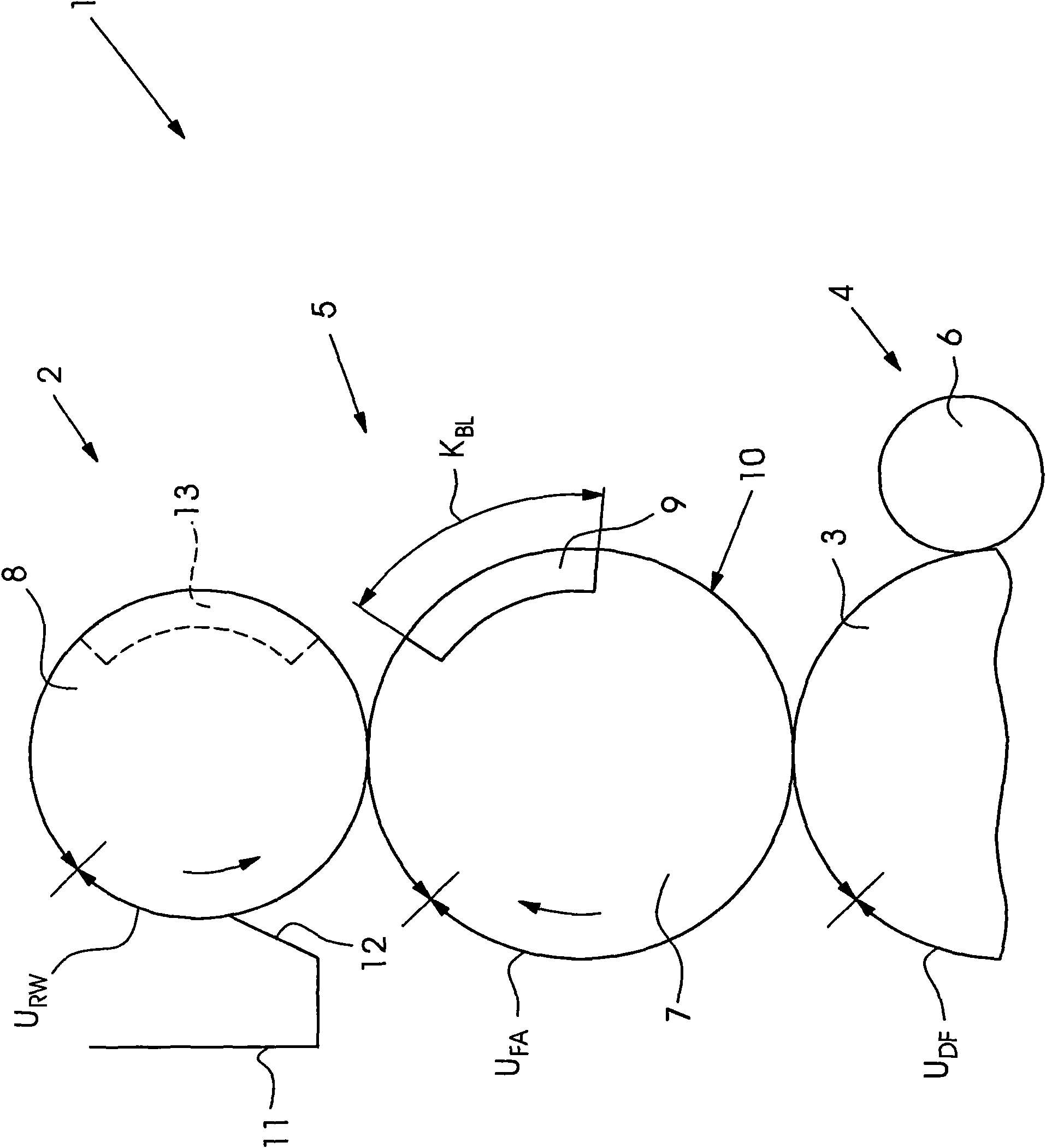
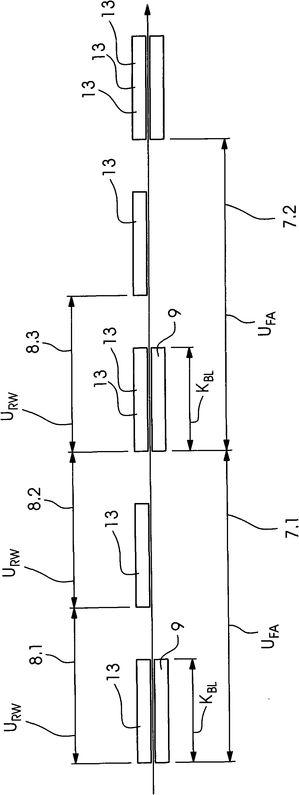
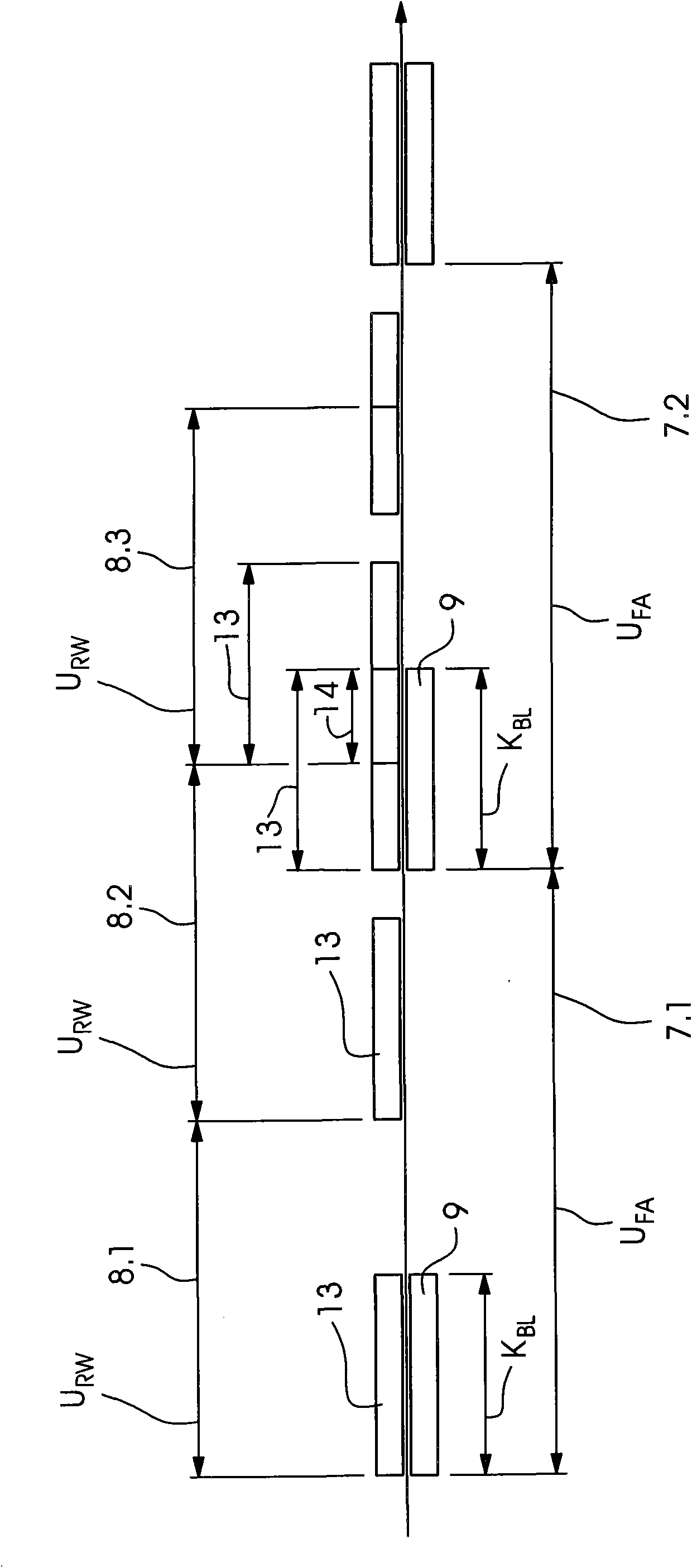
[0019] figure 1 A printing press 1 for offset offset printing on sheets is shown in section. A printing unit 2 of the printing press 1 is partially shown in this section. The printing unit comprises a printing form cylinder 3 , a dampening unit 4 for dampening the printing form cylinder 3 and an inking unit 5 for inking the printing form cylinder 3 . The plate cylinder 3 has an outer circumference U DF . The dampening unit 4 is a roller dampening unit and, in addition to a dipping roller, a metering roller and a transfer roller not shown in the figure, also has a dampening roller 6 which rests against the plate cylinder during printing operation. 3 on. The inking unit 5 includes an inking roller 7 , which also rests against the plate cylinder 3 during the printing operation, and also includes an anilox roller 8 abutting against th...


PUM


Abstract

A printing unit (2) contains a dampening unit (4) and an inking unit (5) which includes a screen roller (8) with a circumference URW and an ink applicator roller (7) with a circumference UFA and a gap having a paper sheet length KBL, the ink applicator roller resting against the screen roller. The circumference URW of the screen roller (8) and the circumference UFA of the ink applicator roller (7) and the paper sheet length KBL of the gap (9) are dimensioned in predetermined proportions relative to each other so as to avoid ghosting.

Description

technical field [0001] The invention relates to a printing unit comprising a dampening unit and an inking unit, the inking unit having an anilox roller with a circumference and an abutting roller with a circumference and a channel Inking roller, the channel has a sheet length. Background technique [0002] Such printing devices are described in EP 0 870 609 A2 and DE 10 2006 050 746 A1. A disadvantage of this prior art printing unit is that the channels produce frame marks which cause visible disturbances in the printed image. The ink form roller does not pick up ink from the anilox roller in the channel area. The ink or more precisely the emulsion remaining in the region of the anilox roller that is complementary to the channels has a different dampening agent content than the remaining region of the anilox roller. If the complementary area rolls over an area of ​​the ink form roller which is located outside the channel, the frame print is transferred from the complement...

Claims


Application Information

Patent Timeline
Patent Type & Authority Applications(China)
IPC IPC(8): B41F7/24
CPCB41F31/00B41F7/24
Inventor W·舍恩伯格D·沙夫拉特H·布特法斯
Owner HEIDELBERGER DRUCKMASCHINEN AG
Why Eureka
Try Eureka