
Method for constructing continuous U-shaped beams

A construction method, U-shaped technology, applied to bridges, bridge construction, erection/assembly of bridges, etc., can solve the problems of long construction period, large bending moment, and low utilization rate of beam body sections, so as to save consumption and reduce span Medium bending moment, considerable economic and social benefits

Inactive Publication Date: 2011-06-08
SOUTHEAST UNIV +1
View PDF4 Cites 5 Cited by
  • Summary
  • Abstract
  • Description
  • Claims
  • Application Information

AI Technical Summary

Problems solved by technology

[0003] The existing U-shaped beam mainly adopts the scheme of simply supported beam, which has the advantages of fast construction speed and high beam quality, and can be constructed in a modular manner. The disadvantage is that the mid-span bending moment is large and the utilization rate of the beam body section is not high
Later, the continuous beam scheme was adopted in some areas, and the construction method of in-situ pouring can solve the shortcomings of the simply supported beam scheme, followed by problems such as long construction period and insufficient quality assurance of in-situ pouring concrete.

Method used


Image

  • Method for constructing continuous U-shaped beams
  • Method for constructing continuous U-shaped beams
  • Method for constructing continuous U-shaped beams

Examples


Embodiment Construction

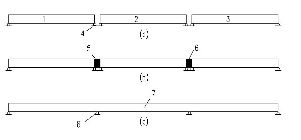
[0011] Below in conjunction with the accompanying drawings, the continuous beam construction method of the present invention is described in detail, and the steps of the construction method of the present invention are roughly the following 3 steps:

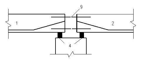
[0012] 1. The simply supported U-shaped beams 1, 2 and 3 required for maintenance are first poured in the beam factory, and the first-stage steel bundle 9 is stretched to meet the force requirements of the beam body during the simple support period and the hoisting process, and then transported to the construction site after reaching the installation requirements. The whole is hoisted in place (temporary support), and the prefabricated beam section is pre-installed on the temporary support 4 according to the simply supported beam to form the simply supported beam section ( figure 1 Take three spans as an example to form simply supported beams 1, 2, 3), and reserve a joint between the U-shaped beam and the U-shaped beam, the width...


PUM


Abstract

The invention discloses a method for constructing continuous U-shaped beams, which comprises the following steps: pouring simply-supported U-shaped beams required for maintenance, reserving plain-bar and prestressed-tendon pipes at the ends of the simply-supported beams, and meeting the stress requirements of the simply-supported beams in the processes of simple supporting and hoisting, after the simply-supported beams meet the installation requirements, transporting the simply-supported beams to the construction site, then hoisting the integral simply-supported beams to the right places by adopting a temporary pedestal, and reserving an operating joint between each two U-shaped beams; stretching a capping hogging-moment prestressed tendon in the operating joint between each two simply-supported U-shaped beams, and connecting a wet joint with the operating seam; and after the wet joint reaches a required strength, removing the temporary pedestal and setting up a permanent pedestal, so that the original simply-supported beams are changed into stressed continuous beams. Compared with the prior art, compared with a simply-supported beam bridge with a same span, a simply-supported beam bridge adopted firstly and a continuous U-shaped beam bridge adopted sequentially in the invention can reduce the span moment, thereby saving the application amounts of steel and concrete, and obtaining the application performance as same as that of the continuous beam bridge under the condition that the technical difficulty is not high and the construction period is short, therefore, the economic benefits and social benefits of the method disclosed by the invention are extremely considerable.

Description

technical field [0001] The invention is suitable for the construction of U-shaped beams used for bridge construction in the traffic field. Background technique [0002] At present, in the field of bridge engineering, especially in the field of urban rail transit, the building height of bridges is often restricted by various factors. U-shaped beams use the bottom plate connecting the webs on both sides to bear the load, which can greatly reduce the building height of the beam body. Solve a series of problems such as insufficient bridge clearance and limited building height. [0003] The existing U-shaped beam mainly adopts the scheme of simply supported beam, which has the advantages of fast construction speed and high beam quality, and can be constructed in a modular manner. The disadvantage is that the mid-span bending moment is large and the utilization rate of the beam section is not high. Later, the continuous beam scheme was adopted in some areas, and the construction ...

Claims


Application Information

Patent Timeline
IPC IPC(8): E01D21/00
Inventor 张继文宋守坛
Owner SOUTHEAST UNIV
Learn More