Eureka AIR delivers breakthrough ideas for toughest innovation challenges, trusted by R&D personnel around the world.

Serially connected casing pipe heat exchange device

A heat exchange device and heat exchanger technology, which is applied to heat exchanger sealing devices, heat exchange equipment, heat exchanger types, etc., can solve the problems of complicated pipelines, complex processing technology, low reliability, etc., and reduce manufacturing costs. , the effect of simplifying the processing process, improving reliability and life

Inactive Publication Date: 2011-06-08
王文杰
View PDF1 Cites 4 Cited by
  • Summary
  • Abstract
  • Description
  • Claims
  • Application Information

AI Technical Summary

Problems solved by technology

[0003] The thermal energy transmitter described in the authorized patent No. 200610033026.1 has high welding cost and complicated processing technology
For other coils or parallel connection of multiple pipes, due to the complexity of the pipes, especially when multiple pipes are connected in parallel, the cost of parallel connection is high
Due to the above reasons, most of the waste heat recovery products in the market are high in price, low in reliability and difficult to promote in the market

Method used


Image

  • Serially connected casing pipe heat exchange device
  • Serially connected casing pipe heat exchange device
  • Serially connected casing pipe heat exchange device

Examples


Embodiment Construction

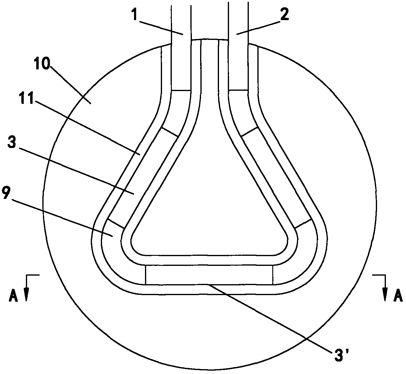
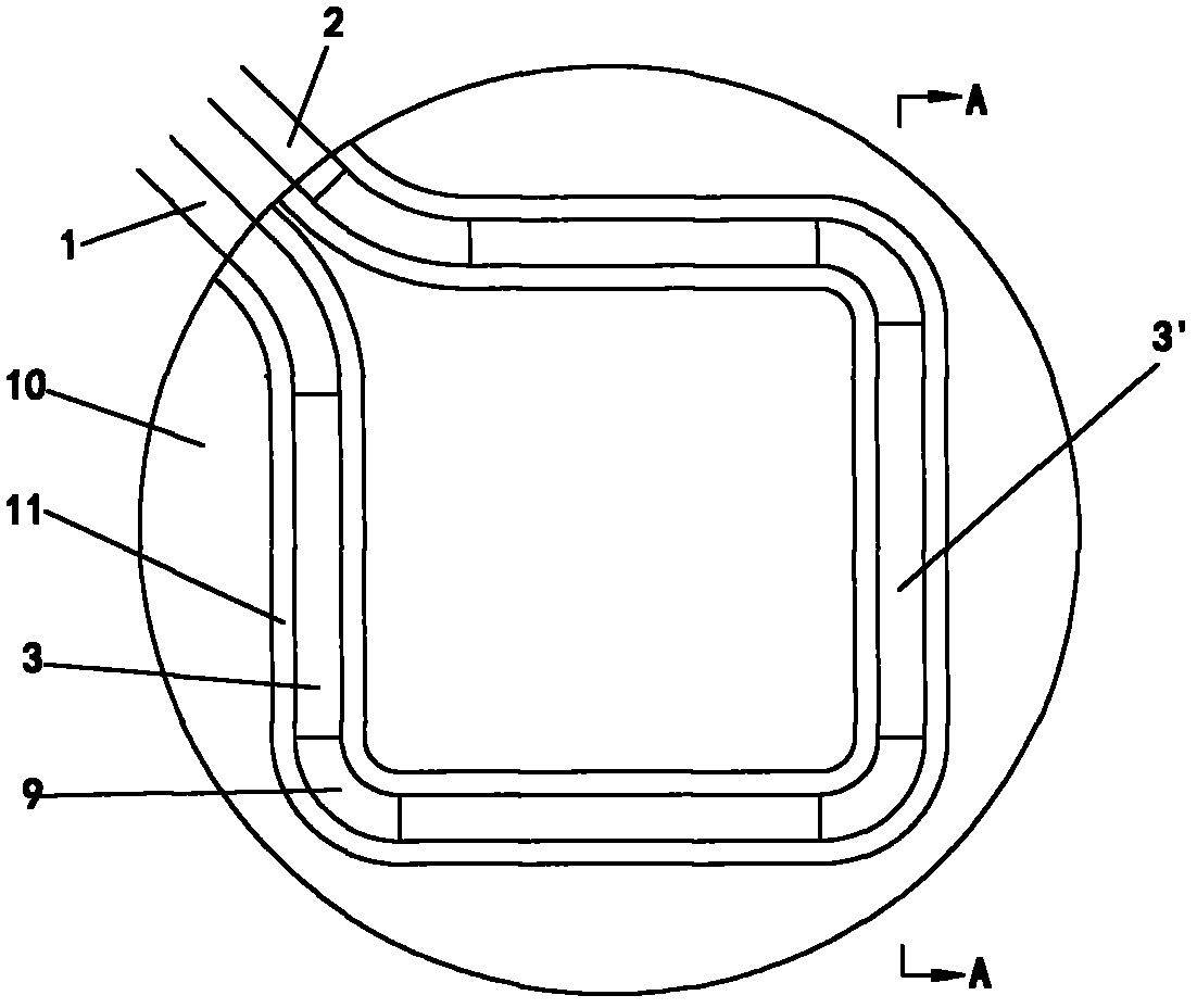
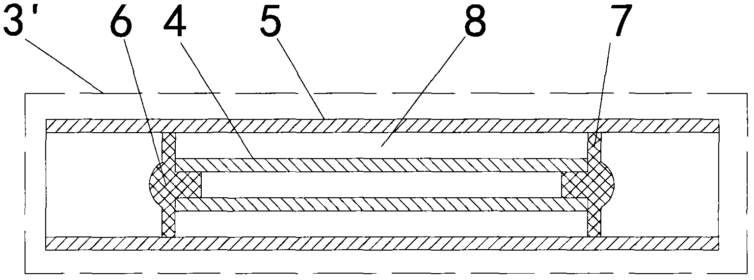
[0013] In the figure, in consideration of household tap water pressure requirements and floor space issues, the casing heat exchanger (3) of this scheme is formed by connecting three or four double-pipe heat exchangers (3)' with connecting pipes (9). The two ends are respectively externally connected to the water inlet port (1) and the water outlet port (2) through connecting pipes. Among them, the double-tube heat exchanger (3)' has selected two thin-walled stainless steel tubes with a wall thickness between 0.4-1.5 mm, wherein the inner tube (4) has an outer diameter of 16-27 mm, and the outer tube (4) has an inner diameter of 19-32mm, both ends of the inner tube (4) are sealed with seals (6) and built into the outer tube (5). In order to avoid affecting the installation performance of the double-tube heat exchanger (3)', the inner tube (4) The length of the outer tube (5) should not be greater than the length of the outer tube (5). The inner tube (4) is coaxially fixed in t...


PUM


Abstract

The invention relates to a serially connected casing pipe heat exchange device which comprises a water inlet port (1), a water outlet port (2), a casing pipe heat exchanger (3) and a support base (10). The serially connected casing pipe heat exchange device is characterized in that the casing pipe heat exchanger (3) is formed by serially connecting a connecting pipe (9) and at least two double-pipe heat exchangers (3)'; each double-pipe heat exchanger (3)' comprises an inner pipe (4), an outer pipe (5), a sealing element (6) and an annular gap (8); each inner pipe (4) is built in the corresponding outer pipe (5); two ends of each inner pipe (4) are respectively sealed by the corresponding sealing element (6); each annular gap (8) is formed between the outer wall of each inner pipe (4) and the inner wall of each outer pipe (5); and two ends of the casing pipe heat exchanger (3) are respectively externally connected to the water inlet port (1) and the water outlet port (2). By using the device, the heat exchange between wasted bath water and tap water is realized, and a better heat exchange effect is achieved.

Description

Technical field [0001] The invention relates to a heat exchanger, in particular to a casing heat exchanger used for waste heat recovery of waste water. Background technique [0002] At present, the known devices for recovering waste heat from showers include tubular heat exchangers and plate heat exchangers. The heat transfer device described in the authorized patent No. 200610033026.1 is actually a single-layer plate heat exchanger (ie A heat exchanger formed by two heat exchange plates), the sealing method is welding. Most of the tube heat exchangers use multi-layer coils, or multiple pipes in parallel, or use corrugated tubes, horizontal tubes, inserts in tubes, inner finned tubes, etc. [0003] The thermal energy transmitter described in the authorized patent No. 200610033026.1 has high welding cost and complicated processing technology. For other methods of coil or parallel connection of multiple pipes, due to the complexity of the pipes, especially when multiple pipe...

Claims


Application Information

Patent Timeline
Patent Type & Authority Applications(China)
IPC IPC(8): F28D7/10F28D1/04F28F11/00
Inventor 王文杰
Owner 王文杰
Why Eureka
Eureka Blog
Learn More