Lens module gluing location device

A lens module and positioning device technology, applied in installation, optics, instruments, etc., can solve problems such as affecting assembly yield, overflowing glue, dispensing misalignment, etc., and achieve the effect of saving dispensing time and accurate dispensing positioning.

Inactive Publication Date: 2011-06-08
HONG FU JIN PRECISION IND (SHENZHEN) CO LTD +1
View PDF2 Cites 7 Cited by
  • Summary
  • Abstract
  • Description
  • Claims
  • Application Information

AI Technical Summary

Problems solved by technology

Due to the tolerance of the depression on the tray during processing, the position of the lens module will form a cumulative tolerance along the X and Y directions. Therefore, it is necessary to correct the position of the dispensing needle before dispensing, otherwise it will easily cause glue overflow or dislocation problems.
In the production process, usually a dispenser needs to dispense glue to the lens modules on several trays, and the tolerance changes between the trays and the position of the lens modules in the tray will cause glue overflow or dispensing Misalignment occurs, making it difficult to achieve precise dispensing and affecting assembly yield
It takes a lot of time to measure the cumulative tolerance for each pallet

Method used


Image

  • Lens module gluing location device
  • Lens module gluing location device
  • Lens module gluing location device

Examples


Embodiment Construction

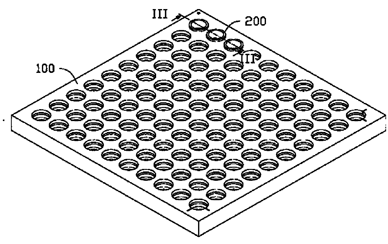
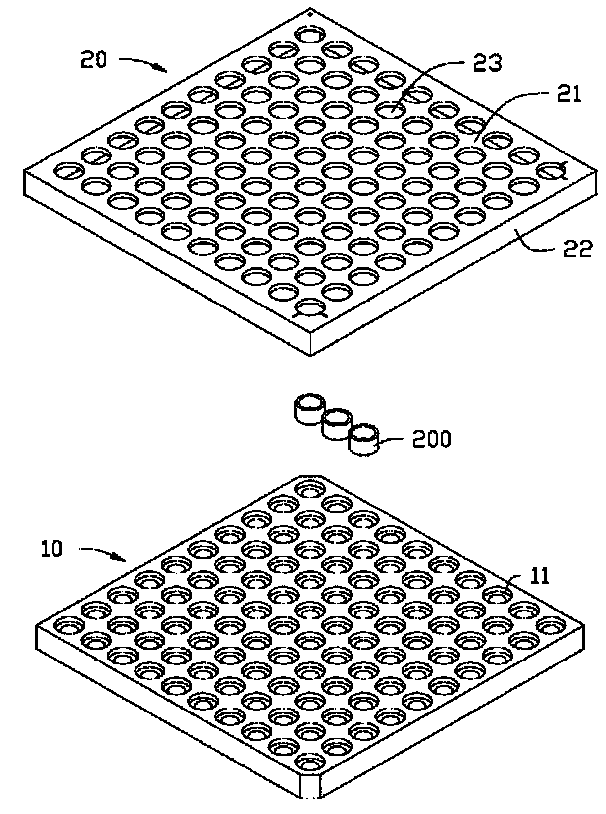
[0015] Such as figure 1 and figure 2 Shown is a preferred embodiment of the dispensing positioning device 100 of the present invention. The glue dispensing positioning device 100 is used to precisely position several lens modules 200, and only a part of the lens modules 200 are shown in the figure. The lens module 200 is in the shape of a cylinder, and optical elements to be dispensed are arranged inside it. The dispensing positioning device 100 includes a tray 10 and a cover 20 disposed on the tray 10 .

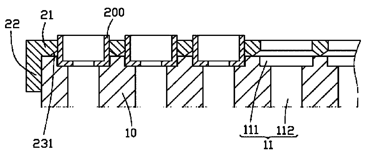
[0016] Please also refer to image 3 , the tray 10 is in the shape of a square, and a plurality of receiving holes 11 are arranged on it for carrying the lens module 200 . Each receiving hole 11 is stepped and runs through the tray 10, including a cylindrical upper hole 111 and a cylindrical lower hole 112, and the diameter of the lower hole 112 is smaller than the diameter of the upper hole 111, that is, the size of the upper hole 111 larger than the size of the lower...


PUM


Abstract

The invention provides a lens module gluing location device which comprises a tray, a plurality of accommodating holes arranged on the tray and used for placing lens modules, and a cover body provided with a plurality of through holes, wherein the through holes of the cover body correspond to the accommodating holes on the tray in a one-to-one manner; the cover body is placed on the tray to allow the lens modules in the accommodating holes on the tray to extend to the through holes of the cover body; and the lens modules on the tray are fixed by the cover body. The gluing location device can be used for greatly reducing the gluing time, and is more accurate in locating the gluing positions of the lens modules.

Description

technical field [0001] The invention relates to the technical field of assembly of lens modules, in particular to a glue dispensing and positioning device for lens modules. Background technique [0002] In recent years, with the development of optical products, the scope of application of lens modules continues to expand, such as digital cameras, mobile phones with camera functions and other electronic products. For electronic products, especially consumer electronic products, the development trend is light weight and thinner, and the corresponding lens modules installed therein are also becoming smaller and smaller, and the requirements for precision are also getting higher and higher. Therefore, the assembly process of the lens module also requires higher accuracy and stability to ensure assembly efficiency and assembly yield. [0003] Lens modules usually include lens barrels, lens groups, spacer rings and filters. The lens group, the spacer ring and the optical filter ...

Claims


Application Information

Patent Timeline
Patent Type & Authority Applications(China)
IPC IPC(8): G02B7/02
Inventor 骆世平
Owner HONG FU JIN PRECISION IND (SHENZHEN) CO LTD
Why Eureka
Try Eureka