Automatic focusing system and method

A technology of automatic focusing and focusing area, applied in focusing devices, optics, cameras, etc., can solve the problems of expensive manufacturing, complicated hardware, slow operation, etc., and achieve the effect of low cost, small extra space, and overcoming expensive manufacturing.

Active Publication Date: 2011-06-08
OMNIVISION TECH INC
View PDF0 Cites 4 Cited by
  • Summary
  • Abstract
  • Description
  • Claims
  • Application Information

AI Technical Summary

Problems solved by technology

[0006] Although autofocus digital imaging devices generally perform better than fixed focus imaging devices, prior art autofocus devices are typically more complex in hardware, more expensive to manufacture and slower in operation than fixed focus devices

Method used


Image

  • Automatic focusing system and method
  • Automatic focusing system and method
  • Automatic focusing system and method

Examples


Embodiment Construction

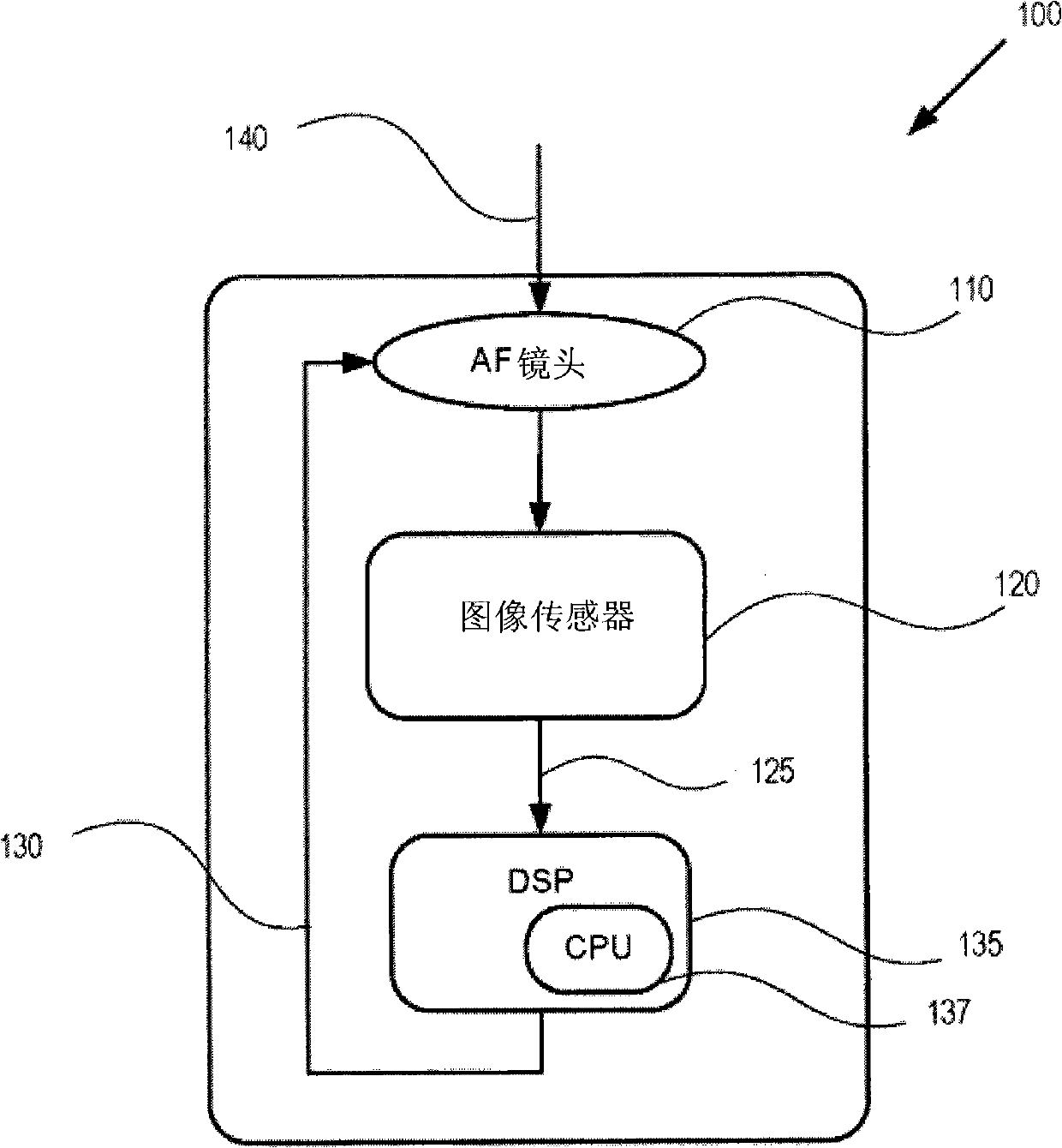
[0029] The auto-focus system disclosed in the present application can be advantageously implemented in a digital imaging device with few or no specialized components to overcome at least some of the problems usually associated with auto-focus systems in the prior art. For example, the system described here determines the best focus position by determining the amount of high spatial frequency information at different focus positions. When the image contains the most high spatial frequency information, it is recognized as the best focusing condition. For example, by applying digital filtering to a part of digitized image data, high spatial frequency information can be measured. The calculated energy of the filtered spectrum can be used to measure the spatial frequency content.

[0030] figure 1 An example of a camera with an autofocus system is shown in. figure 1 A camera system 100 is represented, which includes an auto focus (AF) lens 110, an image sensor 120, and a digital sign...


PUM


Abstract

The invention discloses a method for an automatic focusing digital imaging device. The method comprises the following steps: (1) capturing a plurality of images, each image being captured at different positions of a lens of the imaging device; (2) generating a high spatial frequency value for each image, each high spatial frequency value representing the high spatial frequency information in the image; (3) determining the image with the largest high spatial frequency value; and (4) adjusting the lens to a position corresponding to the position at which the image with the largest high spatial frequency value is captured.

Description

Invention field [0001] The invention relates to an automatic focusing method and system used in a digital imaging device. Background technique [0002] Digital imaging devices can be classified as auto-focus (auto-focus) or fixed-focus devices. Fixed focusing devices usually cannot adjust the lens or change the aperture, but instead rely on the large depth of field where the target appears in focus. Although the images captured by fixed focus devices are acceptable in many situations, they are not as sharp as those captured by autofocus devices. [0003] The image captured at the focal point of the lens is a sharp-focus image. Here, the focal point refers to the point on the lens axis of the camera where light converges. However, even if the target is not in focus, if the target is in the depth of field of the lens, a sufficiently clear target image, that is, a sharp focus image, can be generated. The depth of field refers to the distance from the camera within which the capture...

Claims


Application Information

Patent Timeline
Patent Type & Authority Applications(China)
IPC IPC(8): G03B13/36
Inventor 朱大国甘龙
Owner OMNIVISION TECH INC
Why Eureka
Try Eureka