Photosensitive drum drive assembly, photosensitive drum and processing cartridge

A technology of photosensitive drum driving and photosensitive drum, which is applied in the fields of optics, electrography, instruments, etc., can solve the problem of increasing the driving force, affecting the service accuracy and life of the axis of the photosensitive drum driving component with 4 round holes on the side wall, and affecting the imaging equipment Drive force output head 8 life and other issues, to avoid friction, simple and practical structure, improve the use of precision and life effect

Active Publication Date: 2011-06-08
PRINT RITE UNICORN IMAGE PROD CO LTD OF ZHUHAI
View PDF6 Cites 18 Cited by
  • Summary
  • Abstract
  • Description
  • Claims
  • Application Information

AI Technical Summary

Problems solved by technology

exist figure 2 In the transmission mode shown, through the protrusion 9 of the photosensitive drum drive assembly, the shaft portion with the outer peripheral surface 93, the gear portion 94, the driving force from the driving force output head 8 is transmitted to the drum body; During the printing process of the imaging device, due to the presence of unstable factors such as vibration in the image forming device and the internal environment of the process box, the axis 81 of the driving force output head 8 cannot completely coincide with the axis 95 of the photosensitive drum driving assembly. When printing starts, The driving force output head 8 drives the photosensitive drum driving assembly to rotate around the axis 81 of the driving force output head 8, and the shaft portion of the photosensitive drum driving assembly rotates around the axis 81 of the driving force output head 8 instead of the axis 95 of the photosensitive drum driving assembly, so that the photosensitive drum The rotational diame

Method used


Image

  • Photosensitive drum drive assembly, photosensitive drum and processing cartridge
  • Photosensitive drum drive assembly, photosensitive drum and processing cartridge
  • Photosensitive drum drive assembly, photosensitive drum and processing cartridge

Examples


Embodiment approach 1

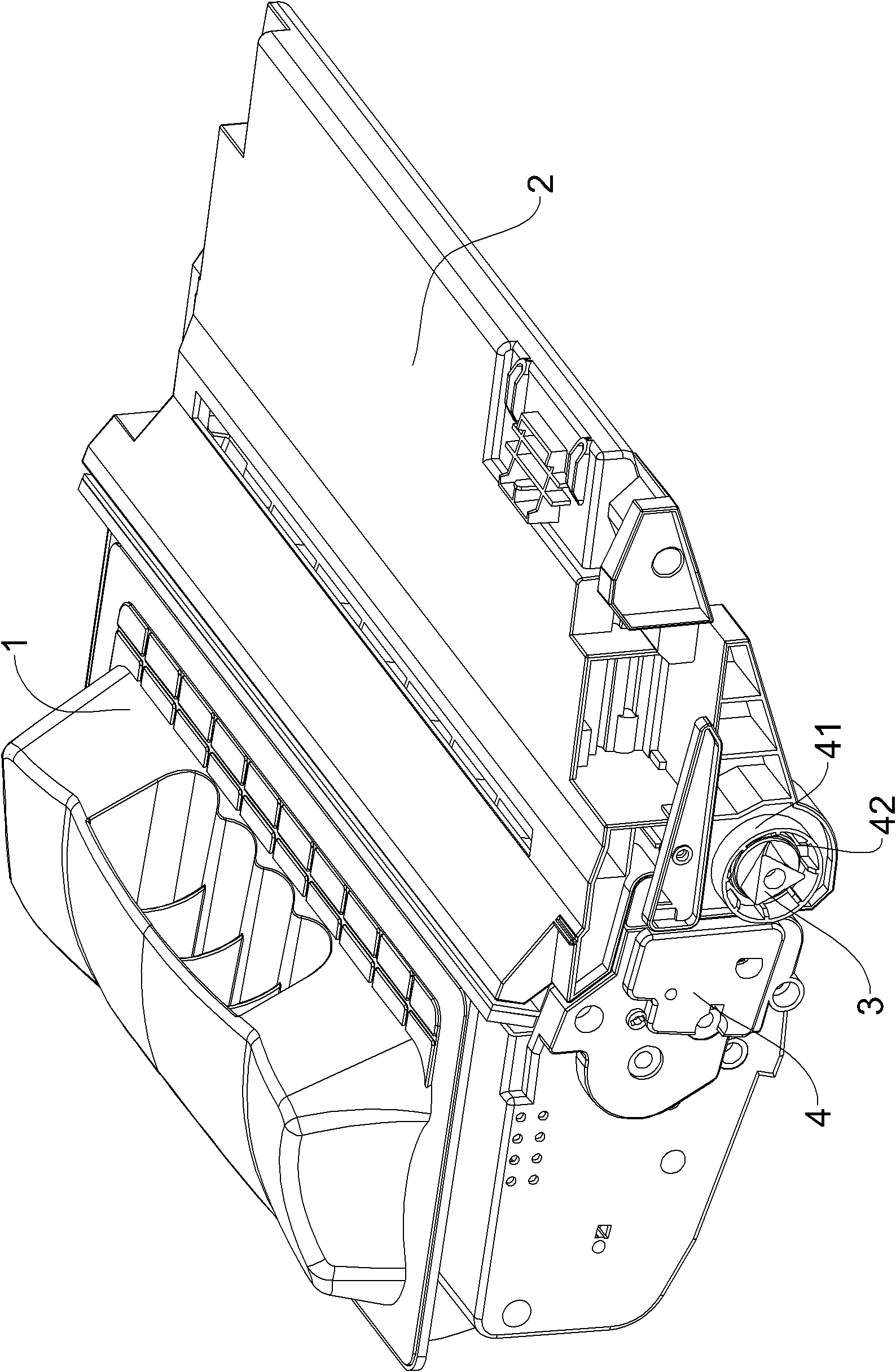
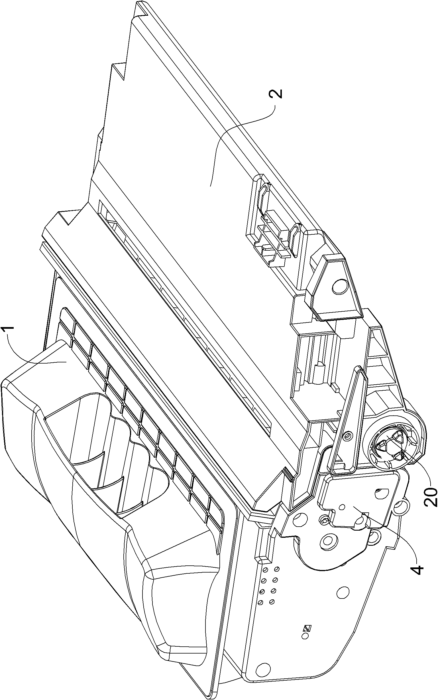
[0029] image 3 It shows a process box applied to imaging equipment according to the present invention. The composition and structure of the process box are roughly the same as those of the traditional process box. It mainly includes a powder bin 1 for containing carbon powder and a waste toner bin 2 for collecting waste powder. The toner bin 1 is provided with components such as a stirring frame, a powder feeding roller, and a developing roller; the waste toner bin 2 is provided with components such as a photosensitive drum 20 , a charging roller, and a cleaning blade. The toner bin 1 and the waste toner bin 2 are connected together by pins or other means. In order to clarify the problem, in each figure of the following embodiments, the driving force output mechanism of the imaging device that does not belong to the present invention is indicated by a two-dot dash line, and the same reference numerals in each figure indicate the same structure.

[0030] see Figure 4 , the ph...

Embodiment approach 2

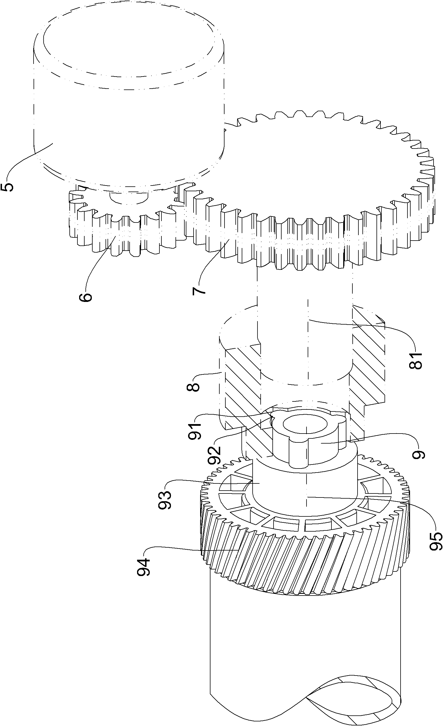
[0037] see Figure 11 and Figure 12 The structure of the photosensitive drum driving assembly 16 of this embodiment is similar to that of the photosensitive drum driving assembly 12 of the first embodiment. It is also composed of a gear 161 and an axial adjustment assembly 162 arranged on the gear 161. The gear 161 can be tightened. Fitted at one end of the drum body 10 , the axial adjustment component 162 can reciprocate relative to the gear 161 along the axial direction of the gear 161 . The axial adjustment assembly 162 includes a driving force receiving head 163 , a driving rod 164 and a toggle pin 165 that can cooperate with the driving force output head 8 .

[0038] The difference is that the driving force receiving head 163 in the photosensitive drum driving assembly 16 of this embodiment is a twisted cylindrical protrusion fixed on the front end of the driving rod 164 .

[0039] see Figure 13 to Figure 16 , when the process cartridge is installed on the image form...


PUM


Abstract

The invention provides a photosensitive drum drive assembly, a photosensitive drum having the drive assembly and a processing cartridge. The photosensitive drum drive assembly comprises a gear capable of being tightly mounted on one end of a drum body, and an axial adjusting assembly capable of making reciprocating movement relative to the gear along the axial direction of the gear, wherein the axial adjusting assembly includes a driving force receiving head capable of being matched with a driving force output head, a driving lever and a shift pin; one end of the driving lever is inserted into the gear along the axial direction; the driving force receiving head is fixed on the outer end of the driving lever and is located outside the gear; the shift pin is fixed on a portion of the driving lever located in the gear; and a stop section capable of being matched with the shift pin to prevent the driving lever from rotating relative to the gear is arranged in the gear. According to the invention, the service life of a motor, a motor transmission gear and the driving force output head of an imaging apparatus can be prolonged, and the use accuracy and the service life of the inner surface of a round hole on the sidewall of the processing cartridge and the outer surface of a shaft of the photosensitive drum drive assembly can be improved.

Description

technical field [0001] The present invention relates to a photosensitive drum driving assembly and a photosensitive drum and a process cartridge having the same. Background technique [0002] Imaging devices such as laser printers, copiers, fax machines, etc. typically use a removable process cartridge as a receptacle for replenishing toner and cooperates with it to form images on media. The driving force required for the moving parts of the process cartridge is provided by a motor within the imaging device. There are mainly two driving force transmission modes between the driving force receiving part of the process box and the driving force output mechanism of the motor: one is the process box disclosed in US Pat. No. 4,829,335. The helical gear at one end of the photosensitive drum is engaged with the helical gear of the photosensitive drum on the process cartridge through the helical gear of the driving part on the imaging device to drive the photosensitive drum to rotat...

Claims


Application Information

Patent Timeline
IPC IPC(8): G03G15/00G03G21/18
CPCG03G15/757G03G21/186
Inventor 苏健强
Owner PRINT RITE UNICORN IMAGE PROD CO LTD OF ZHUHAI
Why Eureka
Try Eureka