Resin retainer for tapered roller bearing, and tapered roller bearing

A technology of tapered roller bearings and tapered rollers, applied in the direction of roller bearings, rolling contact bearings, bearings, etc., can solve the problems of low production efficiency, damage to the ridge line of the column part 102, etc., so as to improve the ease of installation and reduce the Rotation torque, effect of reducing stirring resistance

Active Publication Date: 2011-06-08
NSK LTD
View PDF9 Cites 27 Cited by
  • Summary
  • Abstract
  • Description
  • Claims
  • Application Information

AI Technical Summary

Problems solved by technology

In addition, since the tapered roller 105 is incorporated while elastically deforming the column portion 102, there is a problem that installation is difficult and production efficiency is low, and the ridge line portion of the column portion 102 may be damaged.

Method used


Image

  • Resin retainer for tapered roller bearing, and tapered roller bearing
  • Resin retainer for tapered roller bearing, and tapered roller bearing
  • Resin retainer for tapered roller bearing, and tapered roller bearing

Examples


no. 1 approach

[0070] First, refer to Figure 1 to Figure 7 The tapered roller bearing according to the first embodiment of the present invention will be described in detail.

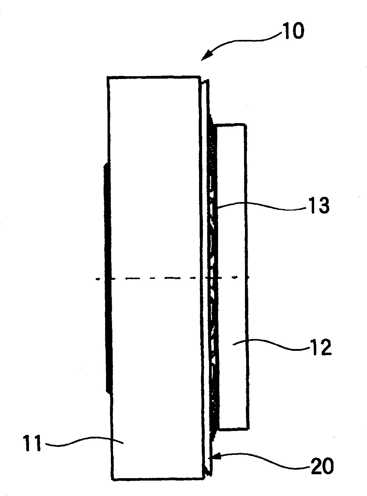
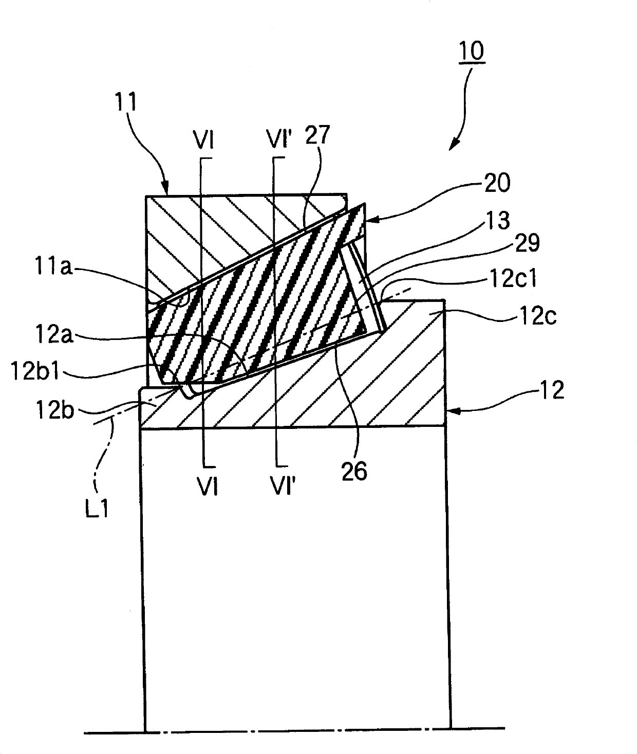
[0071] Such as figure 1 and figure 2 As shown, the tapered roller bearing 10 of the first embodiment has: the outer ring 11, which has an outer ring raceway surface 11a on the inner peripheral surface; the inner ring 12, which has an inner ring raceway surface 12a on the outer peripheral surface, and the inner ring raceway The surface 12a has a small flange portion 12b and a large flange portion 12c on both axial sides; a plurality of tapered rollers 13 are rotatably arranged between the outer ring raceway surface 11a and the inner ring raceway surface 12a; resin The cage 20 holds a plurality of tapered rollers 13 at predetermined intervals in the circumferential direction.

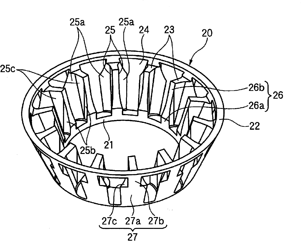
[0072] Such as image 3 , Figure 5 As shown in (a) and (b), the retainer 20 has: a small-diameter annular portion 21 having a predetermi...

no. 2 approach

[0095] Next, refer to Figure 12 (a)~ Figure 13 A tapered roller bearing according to a second embodiment of the present invention will be described. In addition, the same code|symbol or appropriate code|symbol is attached|subjected to the part equivalent or the same as 1st Embodiment, and the description is simplified or abbreviate|omitted.

[0096] Such as Figure 12 (a)~ Figure 13 As shown, the resin cage 20f of the second embodiment has a chamfered portion 35 formed of two arcs between the inner peripheral surface 26 of the column portion 23 and the inner peripheral surface 33 of the large-diameter annular portion 22 . The chamfered portion 35 is composed of two arc portions, a first arc portion 35a and a second arc portion 35b provided on the side of the large-diameter annular portion 22, wherein the first arc portion 35a is provided on the The support portion 36 (roller guide surface) for supporting the tapered roller 13 of the cage 20f is located closer to the inn...

no. 3 approach

[0106] Next, refer to Figure 17 and Figure 18 A resin cage for a tapered roller bearing according to a third embodiment of the present invention will be described. In addition, the same code|symbol or appropriate code|symbol is attached|subjected to the part equivalent or the same as 1st Embodiment, and the description is simplified or abbreviate|omitted.

[0107] Such as Figure 17As shown, in the resin cage 20o of the third embodiment, the inside inner peripheral surface 26 of the column portion 23 is provided to be shorter than 1 / 2 of the axial length L of the column portion 23 as a single arc portion, The chamfered portion 35 i is formed between the inner inner peripheral surface 26 and the axially outer surface 34 a of the large-diameter annular portion 22 . Therefore, the support portion 36 where the cage 20 o supports the tapered roller 13 becomes shorter than 1 / 2 of the axial length of the tapered roller 13 . This kind of cage 20o maintains the posture of the tap...


PUM


Abstract

A resin retainer for a tapered roller bearing and the tapered roller bearing which are configured such that a space in the tapered roller bearing is reduced, stir resistance of lubricating oil contained in the bearing is reduced, and easiness of mounting of tapered rollers into the bearing is enhanced. A resin retainer (20) for a tapered roller bearing is provided with a small-diameter annular section (21), a large-diameter annular section (22), and struts (23) for interconnecting both the annular sections (21, 22). The struts (23) are each provided with a pair of circumferential side surfaces (25) respectively having roller guide surfaces (27), and also each provided with an inner peripheral surface (26) having a circumferential width smaller on the large-diameter annular section (22) side than on the small-diameter annular section (21) side. Between adjacent struts (23) is provided a retaining region (Ar) having, between the opposed circumferential side surfaces (25) of the adjacent struts (23), an outer-diameter-side pocket width (W1) and an inner-diameter-side pocket width (W2) which are set less than a diameter (D) of the tapered rollers.

Description

technical field [0001] The present invention relates to a resin-made cage for a tapered roller bearing and a tapered roller bearing, and more particularly to a resin-made cage and a tapered roller bearing for a transmission or a differential gear, etc., which are used in conditions where there is a lot of lubricating oil. roller bearings. Background technique [0002] Various resin-made cages have been proposed as conventional tapered roller bearings (for example, refer to Patent Documents 1 to 4). For example, in the holder 101 described in Patent Document 1, as Figure 25 As shown in (a) and (b), by increasing the radial dimension of the column portion 102, the space volume in the tapered roller bearing 100 is reduced, thereby reducing the amount of lubricating oil in the bearing and reducing the stirring resistance. In addition, on the inner peripheral surface side of the column portion 102, a guide groove 103 whose diameter is enlarged from the small-diameter annular po...

Claims


Application Information

Patent Timeline
Patent Type & Authority Applications(China)
IPC IPC(8): F16C33/46F16C19/36F16C33/56F16C33/66
CPCF16C33/6681F16C33/4635F16C33/4682F16C19/364F16C2361/61F16C2220/04F16C2240/70F16C33/66F16C33/46F16C33/56F16C19/36
Inventor 竹内匠山田亮辅汤川谨次斋藤智治前岛大纪中井贵美子
Owner NSK LTD
Why Eureka
Try Eureka