Resin retainer for tapered roller bearing, and tapered roller bearing
A technology of tapered roller bearings and tapered rollers, applied in the direction of roller bearings, rolling contact bearings, bearings, etc., can solve the problems of low production efficiency, damage to the ridge line of the column part 102, etc., so as to improve the ease of installation and reduce the Rotation torque, effect of reducing stirring resistance
- Summary
- Abstract
- Description
- Claims
- Application Information
AI Technical Summary
Problems solved by technology
Method used
Image
Examples
no. 1 approach
[0070] First, refer to Figure 1 to Figure 7 The tapered roller bearing according to the first embodiment of the present invention will be described in detail.
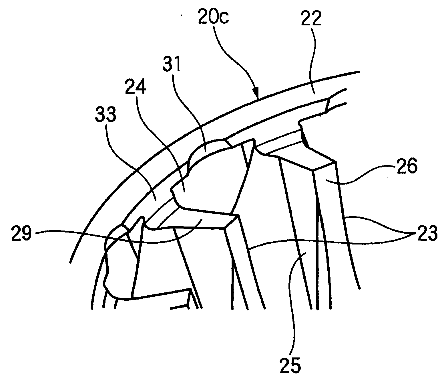
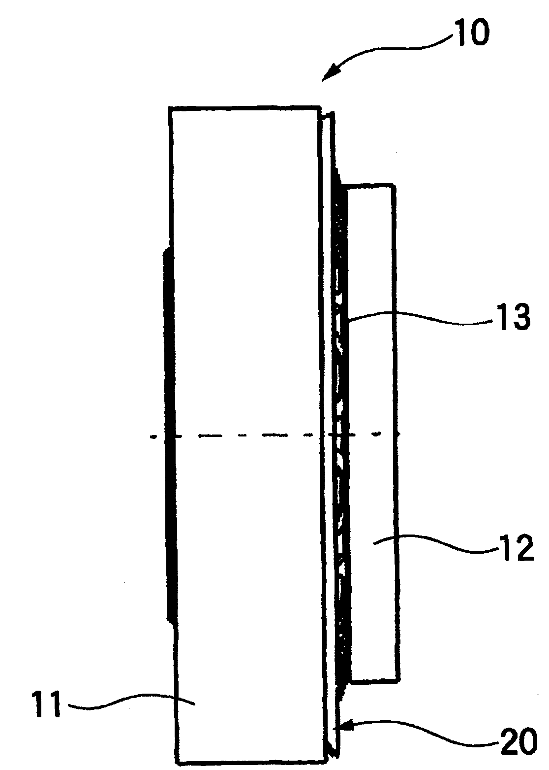
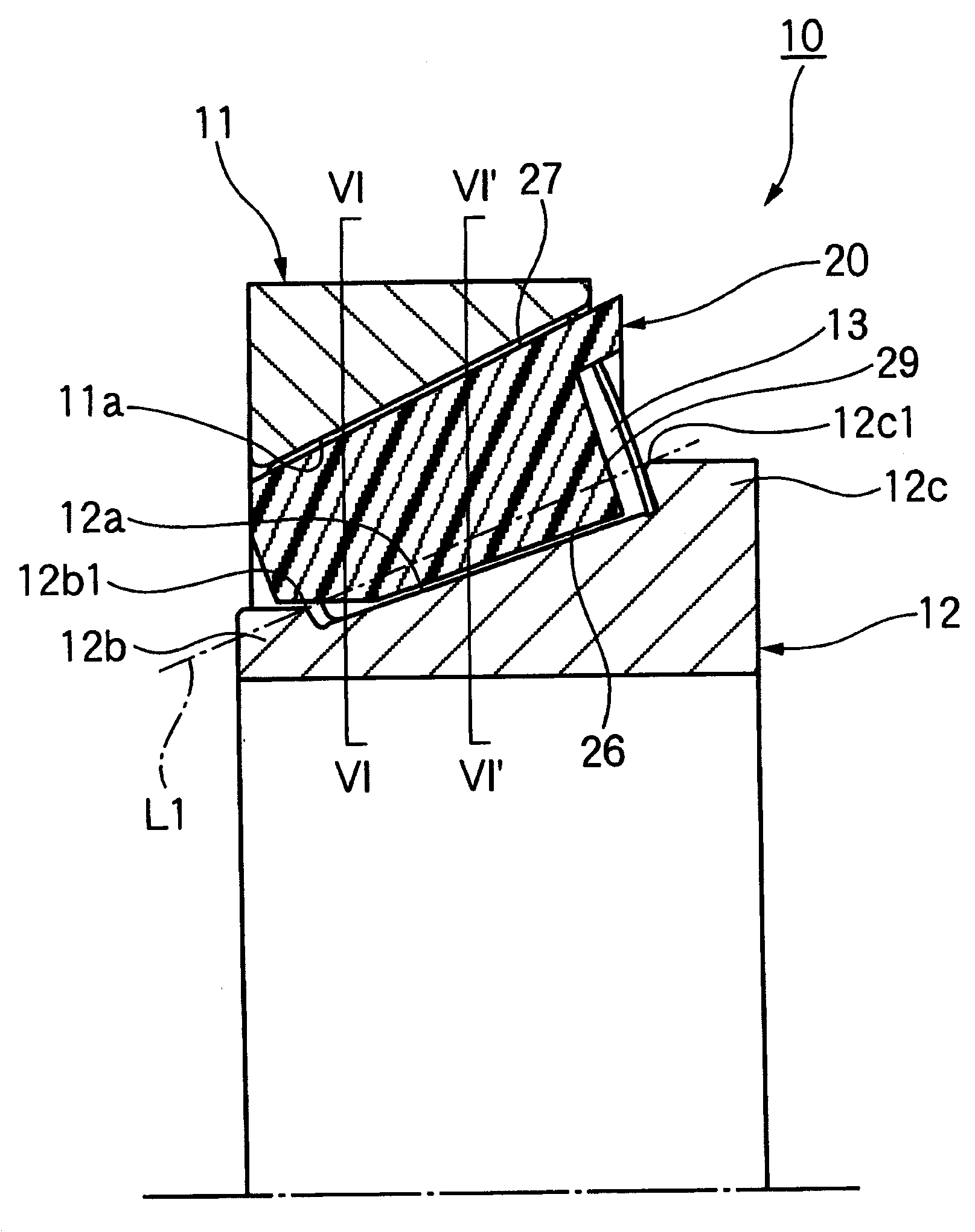
[0071] Such as figure 1 and figure 2 As shown, the tapered roller bearing 10 of the first embodiment has: the outer ring 11, which has an outer ring raceway surface 11a on the inner peripheral surface; the inner ring 12, which has an inner ring raceway surface 12a on the outer peripheral surface, and the inner ring raceway The surface 12a has a small flange portion 12b and a large flange portion 12c on both axial sides; a plurality of tapered rollers 13 are rotatably arranged between the outer ring raceway surface 11a and the inner ring raceway surface 12a; resin The cage 20 holds a plurality of tapered rollers 13 at predetermined intervals in the circumferential direction.
[0072] Such as image 3 , Figure 5 As shown in (a) and (b), the retainer 20 has: a small-diameter annular portion 21 having a predetermi...
no. 2 approach
[0095] Next, refer to Figure 12 (a)~ Figure 13 A tapered roller bearing according to a second embodiment of the present invention will be described. In addition, the same code|symbol or appropriate code|symbol is attached|subjected to the part equivalent or the same as 1st Embodiment, and the description is simplified or abbreviate|omitted.
[0096] Such as Figure 12 (a)~ Figure 13 As shown, the resin cage 20f of the second embodiment has a chamfered portion 35 formed of two arcs between the inner peripheral surface 26 of the column portion 23 and the inner peripheral surface 33 of the large-diameter annular portion 22 . The chamfered portion 35 is composed of two arc portions, a first arc portion 35a and a second arc portion 35b provided on the side of the large-diameter annular portion 22, wherein the first arc portion 35a is provided on the The support portion 36 (roller guide surface) for supporting the tapered roller 13 of the cage 20f is located closer to the inn...
no. 3 approach
[0106] Next, refer to Figure 17 and Figure 18 A resin cage for a tapered roller bearing according to a third embodiment of the present invention will be described. In addition, the same code|symbol or appropriate code|symbol is attached|subjected to the part equivalent or the same as 1st Embodiment, and the description is simplified or abbreviate|omitted.
[0107] Such as Figure 17As shown, in the resin cage 20o of the third embodiment, the inside inner peripheral surface 26 of the column portion 23 is provided to be shorter than 1 / 2 of the axial length L of the column portion 23 as a single arc portion, The chamfered portion 35 i is formed between the inner inner peripheral surface 26 and the axially outer surface 34 a of the large-diameter annular portion 22 . Therefore, the support portion 36 where the cage 20 o supports the tapered roller 13 becomes shorter than 1 / 2 of the axial length of the tapered roller 13 . This kind of cage 20o maintains the posture of the tap...
PUM
 Abstract
Description
Claims
Application Information
 - R&D
- Intellectual Property
- Life Sciences
- Materials
- Tech Scout
- Unparalleled Data Quality
- Higher Quality Content
- 60% Fewer Hallucinations
Browse by: Latest US Patents, China's latest patents, Technical Efficacy Thesaurus, Application Domain, Technology Topic, Popular Technical Reports.
© 2025 PatSnap. All rights reserved.Legal|Privacy policy|Modern Slavery Act Transparency Statement|Sitemap|About US| Contact US: help@patsnap.com


