

Ladle nozzle casting combined drainage plug
A nozzle and ladle technology, which is applied in the field of auxiliary devices, can solve the problems of large difference in shape between the plug and the inner wall of the nozzle, inconvenient processing and production, storage and transportation, and the nozzle is easily covered or blocked, so as to improve the success rate of casting and facilitate processing The effect of making and enhancing the stability of the installation
Inactive Publication Date: 2011-06-15
马鞍山中冶钢铁冶金高新技术有限公司 +1
View PDF7 Cites 11 Cited by
- Summary
- Abstract
- Description
- Claims
- Application Information
AI Technical Summary
Problems solved by technology
Although the drainage agent plug has a simple structure, is easy to manufacture, is convenient to operate, and saves time, it still has obvious defects: the drainage agent plug is slender, the upper part of the nozzle is too small, and its strength is low, so it cannot withstand the impact and weight of debris , the nozzle is still easy to be covered or blocked, and its advantages are difficult to play
The disadvantages are that the structure is unreasonable, and the processing, production, storage and transportation are inconvenient; the consumption of materials for the production of the cylinder is large, and the amount of drainage sand is large; the shape of the plug and the inner wall of the nozzle is very different. The plug is cylindrical, and the inner wall of the nozzle is funnel-shaped. Or the longitudinal section of the inner wall is hyperbolic, and there is no fixing mechanism between the plug post and the nozzle, and the combination is still unstable
When the ladle is lying on its back, the drainage plug has less force in the nozzle, and after the guide rod is removed, the drainage plug is easy to slide out of the nozzle; during the ladle turning and transporting process, due to the vibration and shaking of the ladle, the fallen residue will be The gap between the plug post and the nozzle enters into the nozzle; when the guide rod is removed, the drainage sand flows into the nozzle from the guide hole, and the plug becomes an empty shell, the strength of the drainage plug is greatly reduced, and the debris and debris will also drain the nozzle. Tightly cover, or block, affect the pouring of molten steel
Method used
View moreImage
Smart ImageViewing Examples

Examples
Embodiment 1
Embodiment 2
Embodiment 3
Login to View More PUM
 Abstract
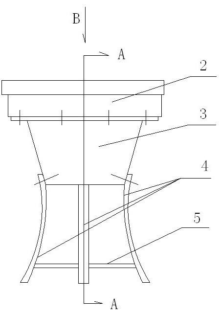
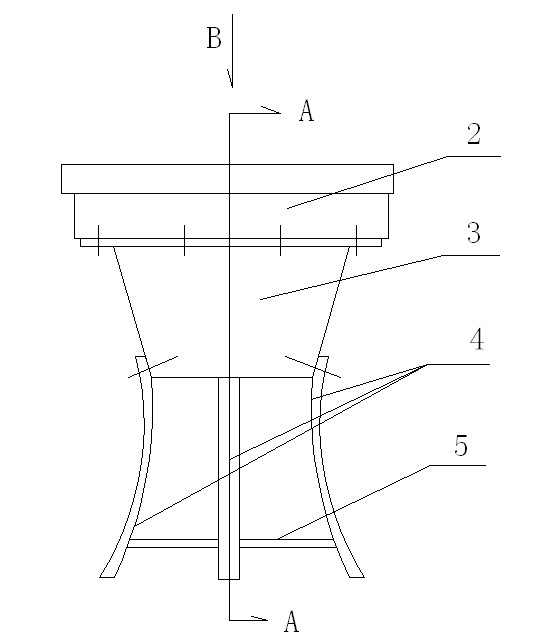
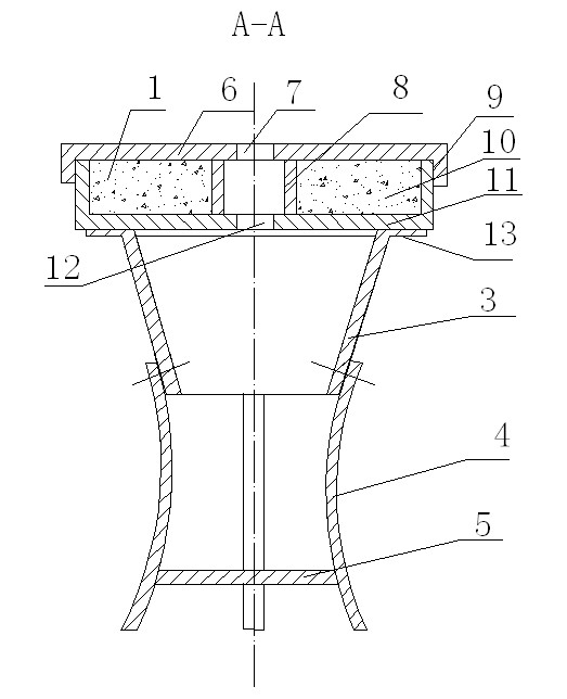
The invention discloses a ladle nozzle casting combined drainage plug, belongs to an accessory device for ladle casting operation, and particularly relates to a ladle brick cup nozzle casting drainage device. The drainage plug is characterized by consisting of a sand storage, an inosculation cylinder, clamping plates and supporting sheets which are connected; the bottom of the sand storage is greater than the diameter of the upper part of a nozzle, a bottom plate is provided with a double-wall annular sand storage chamber in which drainage sand is filled, and a plug cover is tightly covered on the sand storage chamber; the bottom plate is provided with a guide hole corresponding to the center of the plug cover; and the inosculation cylinder is a thin-shell cylinder equivalent to the shape of the inner wall of the nozzle, the upper part of the inosculation cylinder is connected with the bottom plate of the sand storage, the lower part of the inosculation cylinder is provided with the clamping plates in pairs, one end of the supporting sheet is fixed on the clamping plate, and the free end of the supporting sheet is jacked on the opposite clamping plate. The drainage plug has novel conception, compact and reasonable structure; the components are manufactured separately, so the drainage plug is convenient to process, store and transport; the drainage plug saves materials, has light weight, and is easily installed accurately in place; the strength of the drainage plug is remarkably increased, so the drainage plug is stable to install and safe and reliable in use; the nozzle is clean, so the casting success rate is improved; and the drainage plug saves the expense and time for treating drainage faults, and is favorable for smooth operation of steelmaking production.
Description
Ladle nozzle casting combined drainage plug technical field The invention belongs to an accessory device for ladle casting operation, in particular to a drainage device for casting at the nozzle of a seat brick at the bottom of a ladle. Background technique Casting is an important technological process in steelmaking production. Successfully smelted molten steel is cast directly or after refining in a ladle. Whether it can be poured smoothly will directly affect production. The nozzle at the bottom of the early ladle used a plug valve to control and adjust the molten steel. Because the movement of the plug is difficult to control, and the plug is easy to fall off, it is gradually abandoned. Most factories now use sliding nozzles to control the casting. In order to prevent the residues in the ladle from clogging the nozzles and ensure smooth pouring, a special person is set up at the tapping point to throw bags of drainage sand to the ladle nozzles in order to start pour...
Claims
Login to View More Application Information
Patent Timeline
 IPC IPC(8): B22D41/48
Inventor周宇明周宇辉
Owner马鞍山中冶钢铁冶金高新技术有限公司