Water balance structure for machine tailstock

A technology of machine tool tailstock and water balance, applied in the direction of tailstock/top, tool holder accessories, metal processing machinery parts, etc. Avoid overweight phenomenon and reduce the effect of matching error

Inactive Publication Date: 2011-06-15
DONGGUAN YUNCHENG PLATE MAKING
View PDF7 Cites 4 Cited by
  • Summary
  • Abstract
  • Description
  • Claims
  • Application Information

AI Technical Summary

Problems solved by technology

[0002] In traditional mechanical processing, due to the uneven internal structure of the blank material itself, some version rollers themselves are seamless steel pipes, and the internal stress distribution is uneven during forming, resulting in easy deviation; when the version roller is clamped, the version roller is clamped , Adjustment of runout and straightness are all done manually by the operator. Due to the limitation of operating experience and proficiency, it is easy to produce human error; moreover, due to the operation or wear of the machine tool itself during the use of the machine tool, after a period of time, the machine tool's The accuracy will change, which will affect the normal operation of the machine tool. After the plate roller is clamped, it will rotate in a biased manner, causing uneven force on the bearing, and the clamp cannot achieve dynamic balance, which will affect the service life of the bearing and the machining accuracy. There is a large centrifugal force, which will cause vibration and matching errors, which will affect the engraving effect and bring inconvenience to the processing

Method used


Image

  • Water balance structure for machine tailstock
  • Water balance structure for machine tailstock
  • Water balance structure for machine tailstock

Examples


Embodiment Construction

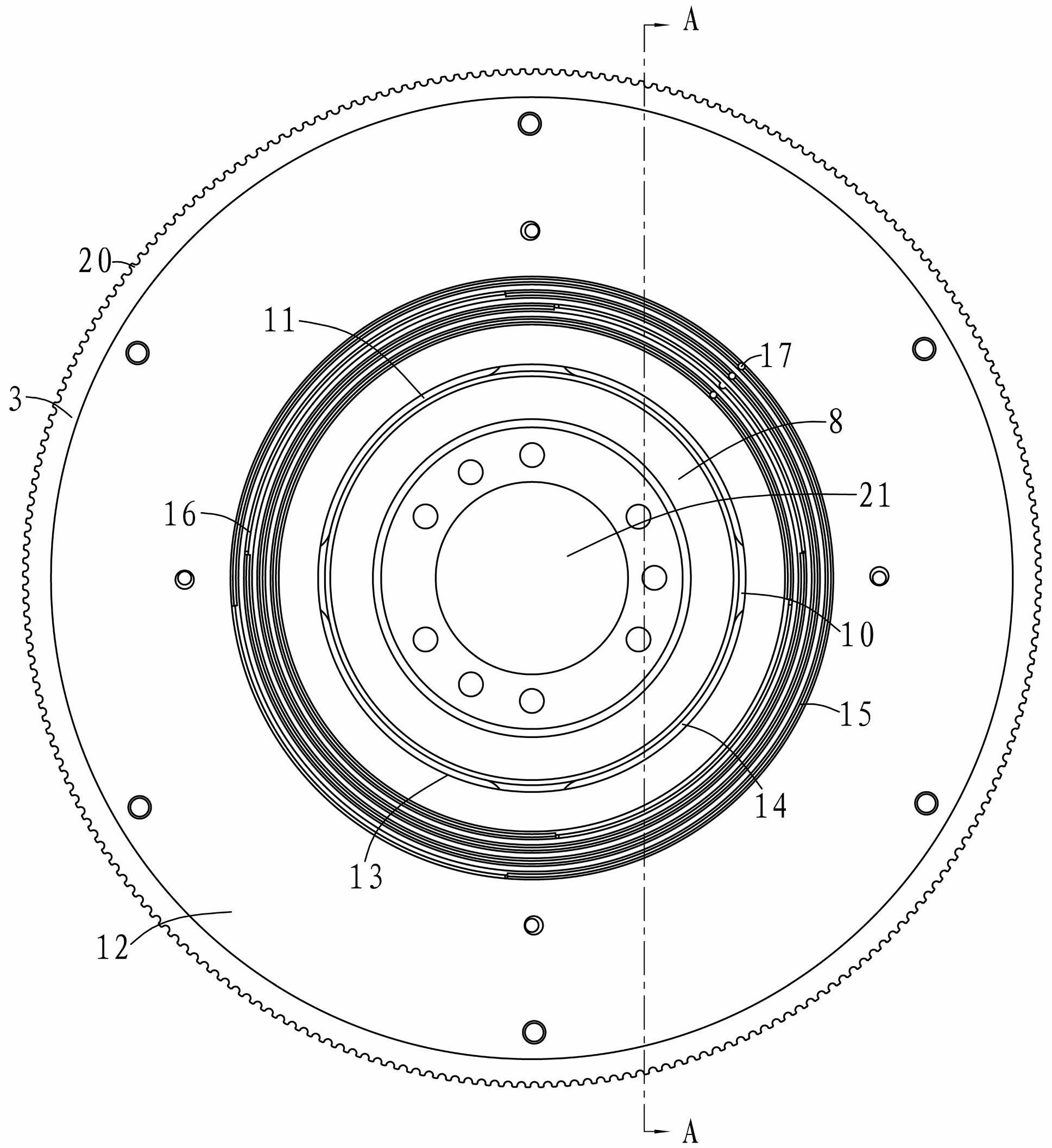
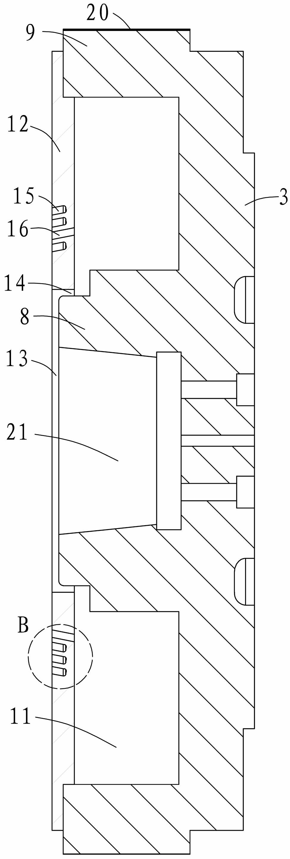
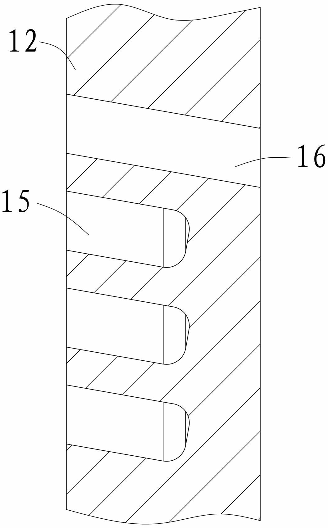
[0029] see Figure 1-8 As shown, the present invention relates to a water balance structure of a machine tool tailstock. A synchronous pulley connection plate (3) is fixedly connected to the clamp (2) of the machine tool tailstock (1). The synchronous pulley connection plate (3) It is connected with the synchronous small pulley (4) connected to the side of the tailstock (1) of the machine tool through the belt (5), and the front cover (6) is connected to the side of the tailstock (1) of the machine tool corresponding to the fixture (2). The belt shell (7) of the tailstock (1) of the machine tool passes through the fixture (2), and is covered on the synchronous pulley connection plate (3) and the small synchronous pulley (4). The synchronous pulley connection plate (3 ) has a mounting groove (8) in the middle, and the cavity formed by the mounting groove (8) and the disc wall (9) is divided into two or more cavities (11) by the rib plate (10). The synchronous pulley connects th...


PUM


Abstract

The invention relates to a water balance structure for a machine tailstock. A clamp arranged on the machine tailstock is fixedly connected with a synchronous belt pulley connection disc; a front end cover is connected to one side corresponding to the clamp; a mounting groove is arranged in the middle part of the synchronous belt pulley connection disc; a cavity formed by the mounting groove and the wall of the synchronous belt pulley connection disc is divided into more that two cavities by rib plates; the open end of the synchronous belt pulley connection disc is provided with a liquid injection disc; a water outlet is arranged between the center hole of the liquid injection disc and the mounting groove arranged on the synchronous belt pulley connection disc; more than two liquid guiding grooves are distributed concentrically on the outer side of the center hole; each liquid guide groove is internally provided with a liquid guide hole and a liquid injection hole; one side of the front end cover is provided with a liquid injection block; and one side of the liquid injection block, which corresponds to the liquid injection disc, is provided with more than two liquid spraying holes. Due to the adoption of the water balance structure for the machine tailstock, the relative dynamic balance between the clamp and a printing roller is ensured, the unbalanced load generated during the rotation of the printing roller is avoided, the matching errors are reduced, the processing precision is improved, the normal service life of a bearing is ensured, the sculpturing effect is improved, and the labor and the materials are saved.

Description

technical field [0001] The invention relates to the field of machining production, in particular to a water balance structure of a tailstock of a machine tool which achieves water balance through liquid weight supplementation, and enables both clamps and plate rollers to perform dynamic balance. Background technique [0002] In traditional mechanical processing, due to the uneven internal structure of the blank material itself, some version rollers themselves are seamless steel pipes, and the internal stress distribution is uneven during forming, resulting in easy deviation; when the version roller is clamped, the version roller is clamped , Adjustment of runout and straightness are all done manually by the operator. Due to the limitation of operating experience and proficiency, it is easy to produce human error; moreover, due to the operation or wear of the machine tool itself during the use of the machine tool, after a period of time, the machine tool's The accuracy will ...

Claims


Application Information

Patent Timeline
Patent Type & Authority Applications(China)
IPC IPC(8): B23B23/00B23Q11/00
Inventor 秦学锋
Owner DONGGUAN YUNCHENG PLATE MAKING
Why Eureka
Try Eureka