Automobile door and cap switchable conveying device
A technology of conveying device and door cover, applied in the direction of conveyor, transportation and packaging, can solve the problems of increasing tooling costs, affecting production efficiency, occupying large production sites, etc., to improve production efficiency, save tooling sites, and reduce tooling costs. Effect
Inactive Publication Date: 2011-06-15
GREAT WALL MOTOR CO LTD
View PDF4 Cites 7 Cited by
- Summary
- Abstract
- Description
- Claims
- Application Information
AI Technical Summary
Problems solved by technology
This situation not only causes a substantial increase in the cost of tooling for the enterprise and occupies a large production site, but also takes up a lot of man-hours during the switching process of each conveying device, which affects production efficiency
Method used
View moreImage
Smart ImageViewing Examples

Examples
Embodiment Construction
Login to View More PUM
 Abstract
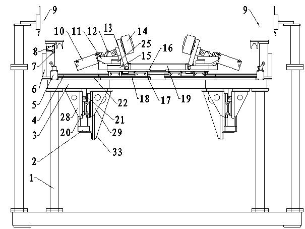
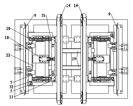
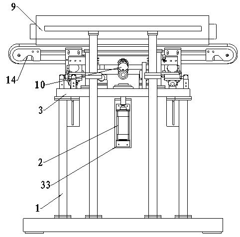
The invention provides an automobile door and cap switchable conveying device. The device consists of a guiding mechanism, a conveying mechanism, a support and an upper frame, wherein the conveying mechanism is positioned on the upper frame, and comprises a left conveying mechanism and a right conveying mechanism; the improved left conveying mechanism and the right conveying mechanism respectively comprise a conveying belt, a horizontal cylinder, a vertical cylinder and an angle cylinder; lift racks are arranged on two sides of the upper frame; the conveying belt is driven by the horizontal cylinder to horizontally move to the lift rack; the vertical cylinder drives the lift rack and the conveying belt to vertically move along with the lift rack; and the angle cylinder drives the conveying belt to adjust angles. The device can be applied to conveying of automobile doors or caps by quick state switching, and ensures that the gravity center position of a workpiece is arranged in the middle of two conveying mechanisms and the conveying belt is contacted with the workpiece surface. Regarding to the appearance changes of the product workpiece or a new product, the conveying device can be put into use by simple adjustment, is advantageous to reducing tooling cost and saving tooling field, and improving the production efficiency.
Description
An automobile door cover switching conveying device technical field The invention relates to a conveying device, in particular to a switchable conveying device for conveying car doors or machine covers on an automobile production line, and belongs to the technical field of automobiles. Background technique In the process of automobile production, there is a process of transporting the processed door or machine cover to the hemming mold equipment to perform hemming treatment on the corresponding parts of the car and cover. The main components of the conveying device include two conveying mechanisms for conveying workpieces, and two guiding mechanisms for guiding workpieces. Among them, the conveying mechanism is a key component to realize workpiece conveying and ensure the stability of workpieces during conveying without surface problems. . Because the shapes of automobile doors and machine covers are different, their sizes, shapes and center of gravity positions are also ...
Claims
Login to View More Application Information
Patent Timeline
 IPC IPC(8): B65G15/20B65G21/12
Inventor 李寅孟树杰司磊张露黄雅雷闫会屯刘超
Owner GREAT WALL MOTOR CO LTD