
Dual-track self-traveling trolley mechanism

A technology of self-propelled trolley and traveling mechanism, which is applied to conveyors, motor vehicles, mechanical conveyors, etc., can solve the problems of unstable operation, large jitter, and high requirements on workpiece positioning accuracy, and achieve the effect of maintaining stability and reducing jitter.

Inactive Publication Date: 2011-06-15
CHERY AUTOMOBILE CO LTD
View PDF6 Cites 18 Cited by
  • Summary
  • Abstract
  • Description
  • Claims
  • Application Information

AI Technical Summary

Problems solved by technology

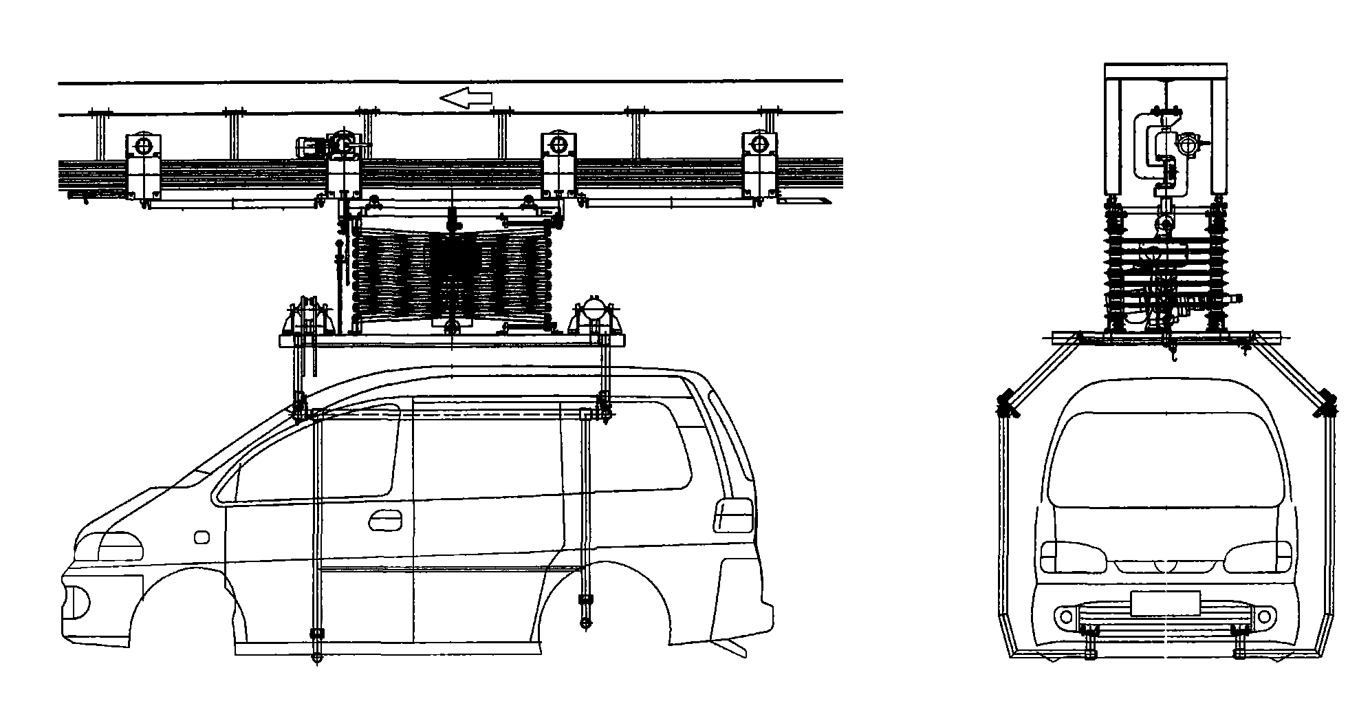
The lifting mechanism of the monorail self-propelled trolley generally uses a lifting hoist or a motor-driven chain structure to achieve lifting, and the lifting hoist or motor-driven chain is prone to horizontal shaking
Therefore, during the operation of the monorail self-propelled trolley, there are disadvantages such as large amount of workpiece shaking, unstable operation, and large vibration during the lifting process. It is not suitable for occasions that require high-speed stable operation and precise positioning during mechanized transportation.
In the automobile manufacturing process, especially some welding assembly assembly stations, the positioning accuracy of the delivered workpieces is high. For example, the body skeleton assembly assembly station requires the positioning accuracy of the side wall to be within 0.5mm , monorail self-propelled trolleys are difficult to meet the requirements

Method used


Image

  • Dual-track self-traveling trolley mechanism
  • Dual-track self-traveling trolley mechanism
  • Dual-track self-traveling trolley mechanism

Examples


Embodiment Construction

[0026] The present invention will be described in detail below in conjunction with specific embodiments and accompanying drawings.

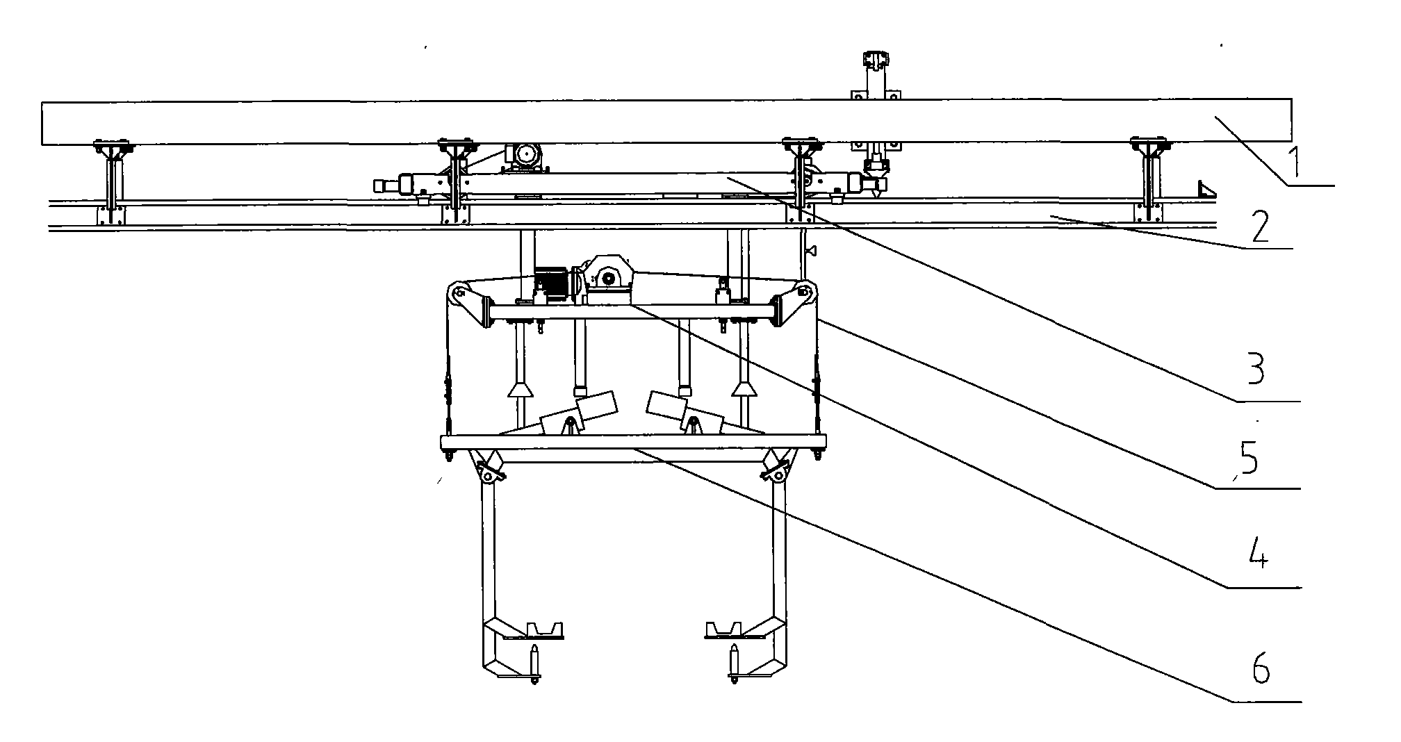
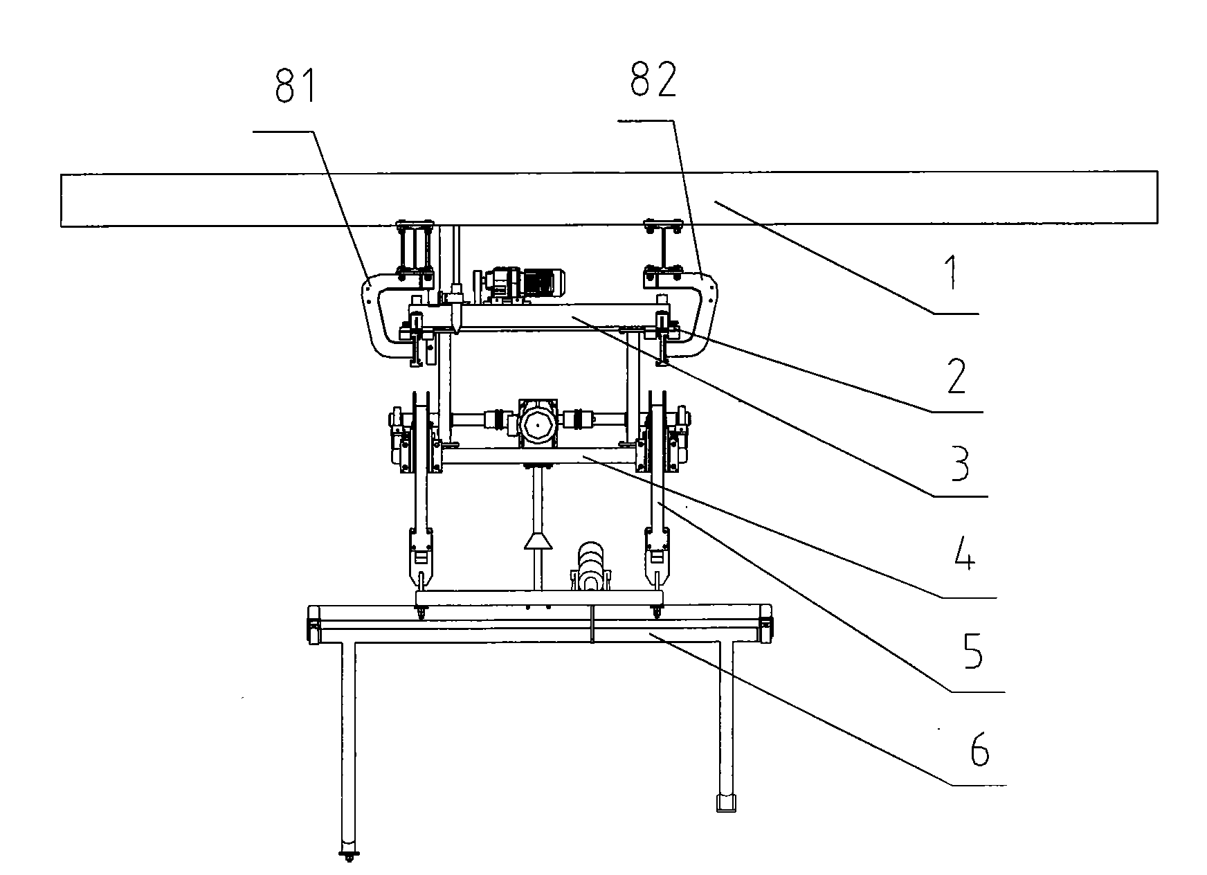
[0027] Such as figure 2 , 3 , 4, the double-track self-propelled trolley mechanism of the present invention comprises the I-beam 1 that is used to fix double-track, double-track 2, the running mechanism 3 that runs on the double-track 2 by traveling wheel, the elevating mechanism 4 that is fixed under the running mechanism 3 and passes activity The sling 5 is connected to the hanger 6 under the lifting mechanism 4, and the traveling mechanism 2 is equipped with a positioning guide sleeve 21, and the positioning guide sleeve 21 cooperates with the positioning guide device 11 fixed on the I-beam 1 for positioning, so The lifting mechanism 4 is a frame type arranged horizontally, and the movable sling 5 has two groups and is arranged in parallel on the mounting support of the frame of the lifting mechanism 4 .

[0028] The working process of the ...


PUM


Abstract

The invention provides a dual-track self-traveling trolley mechanism which is stable in running, low in oscillation level and vibration degree in a lifting process, and precise in positioning. The dual-track self-traveling trolley mechanism comprises I-shaped steel for fixing dual tracks, dual tracks, a traveling mechanism traveling on the dual tracks through traveling wheels, a lifting mechanism fixed below the traveling mechanism and a lifting appliance connected below the lifting mechanism through movable hanging strips, wherein the traveling mechanism is provided with a positioning guiding sleeve matched with a positioning guiding device on the I-shaped steel for positioning, the lifting mechanism is of a horizontal framework type, and two groups of the movable hanging strip are arranged on mounting supports on two sides of the framework of the lifting mechanism in parallel. Compared with the traditional single-track self-traveling trolley mechanism which is lifted by a chain structure driven by a lifting block or an electric motor, the dual-track self-traveling trolley mechanism has the advantages that the oscillation of the lifting appliance in a traveling process and the vibration of the lifting appliance in a lifting process can be alleviated, and the lifting appliance can be kept stable and can be positioned accurately.

Description

technical field [0001] The invention relates to the technical field of self-propelled trolley conveyor lines, in particular to a double-track self-propelled trolley mechanism. Background technique [0002] The self-propelled trolley conveyor line is widely used in the transfer and storage of the lower body assembly, the left and right side panels, the roof assembly, the body frame assembly, the body in white and the painted body in the automobile manufacturing process. Its main features are high conveying efficiency, low failure rate, low noise, no pollution, convenient equipment maintenance, high degree of automation, and the ability to realize multi-vehicle mixed line production. The currently widely used self-propelled trolley conveyor lines are mainly monorail self-propelled trolley conveyor lines. The lifting mechanism of the monorail self-propelled trolley generally uses a lifting hoist or a motor-driven chain structure to achieve lifting, and the lifting hoist or mot...

Claims


Application Information

Patent Timeline
IPC IPC(8): B65G35/00B62D65/18
Inventor 梅绍乔冯振方昌虎
Owner CHERY AUTOMOBILE CO LTD
Learn More