
Lower supported hanging basket in bridge construction and application thereof

A technology for bridge construction and beams, which is applied in the direction of bridges, bridge construction, erection/assembly of bridges, etc. It can solve the problems of slow movement of the upper-loaded hanging basket, complex setting of anti-tensioning supports, and low reuse rate of slideways, etc., to achieve The shape of the hanging basket is stable, the effect of saving pre-embedded steel materials and preset procedures, and shortening the walking time

Active Publication Date: 2011-06-15
THE FIRST ENG CO LTD OF CTCE GRP
View PDF7 Cites 22 Cited by
  • Summary
  • Abstract
  • Description
  • Claims
  • Application Information

AI Technical Summary

Problems solved by technology

[0004] 1. It is necessary to pre-embed a large number of precision-rolled rebars during construction. These pre-embedded parts are buried in the box girder and cannot be recycled, resulting in waste of materials;
[0005] 2. The pre-embedded precision of the glideway anchoring steel bars is required to be high, while the reuse rate of the slideway is extremely low;
[0006] 3. The setting of the anti-pull support is relatively complicated and uneconomical;
[0007] 4. The space at the top of the beam is limited by the main truss structure of the hanging basket, so that the steel skeleton of the beam can only be bound on-site on the bottom formwork platform according to the traditional method, which is difficult to operate and affects the construction period;
[0008] 5. The top-supporting hanging basket moves slowly, and it must be completed repeatedly through the anti-pull support during the deformation process, which is time-consuming and labor-intensive;

Method used


Image

  • Lower supported hanging basket in bridge construction and application thereof
  • Lower supported hanging basket in bridge construction and application thereof
  • Lower supported hanging basket in bridge construction and application thereof

Examples


Embodiment Construction

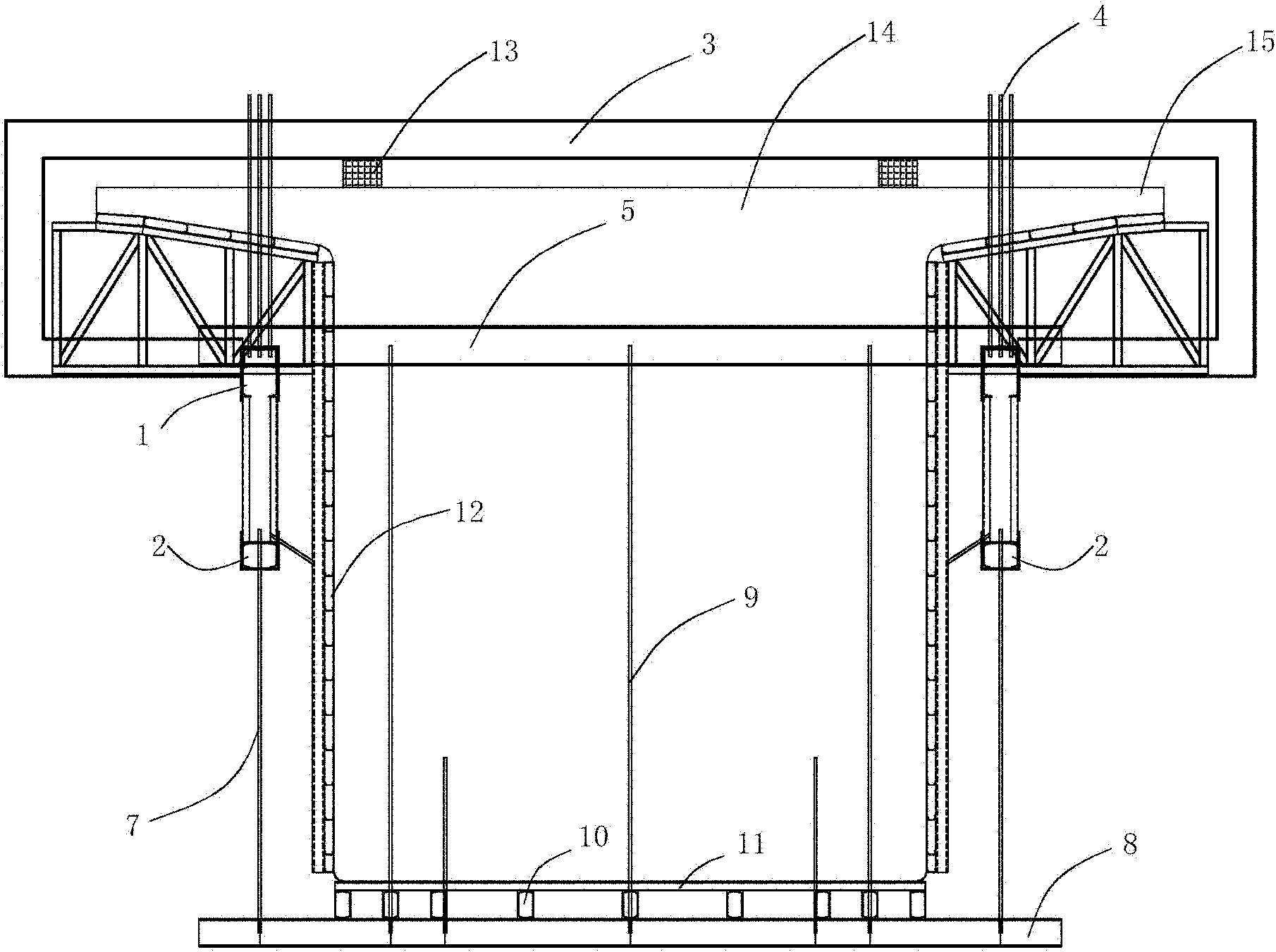
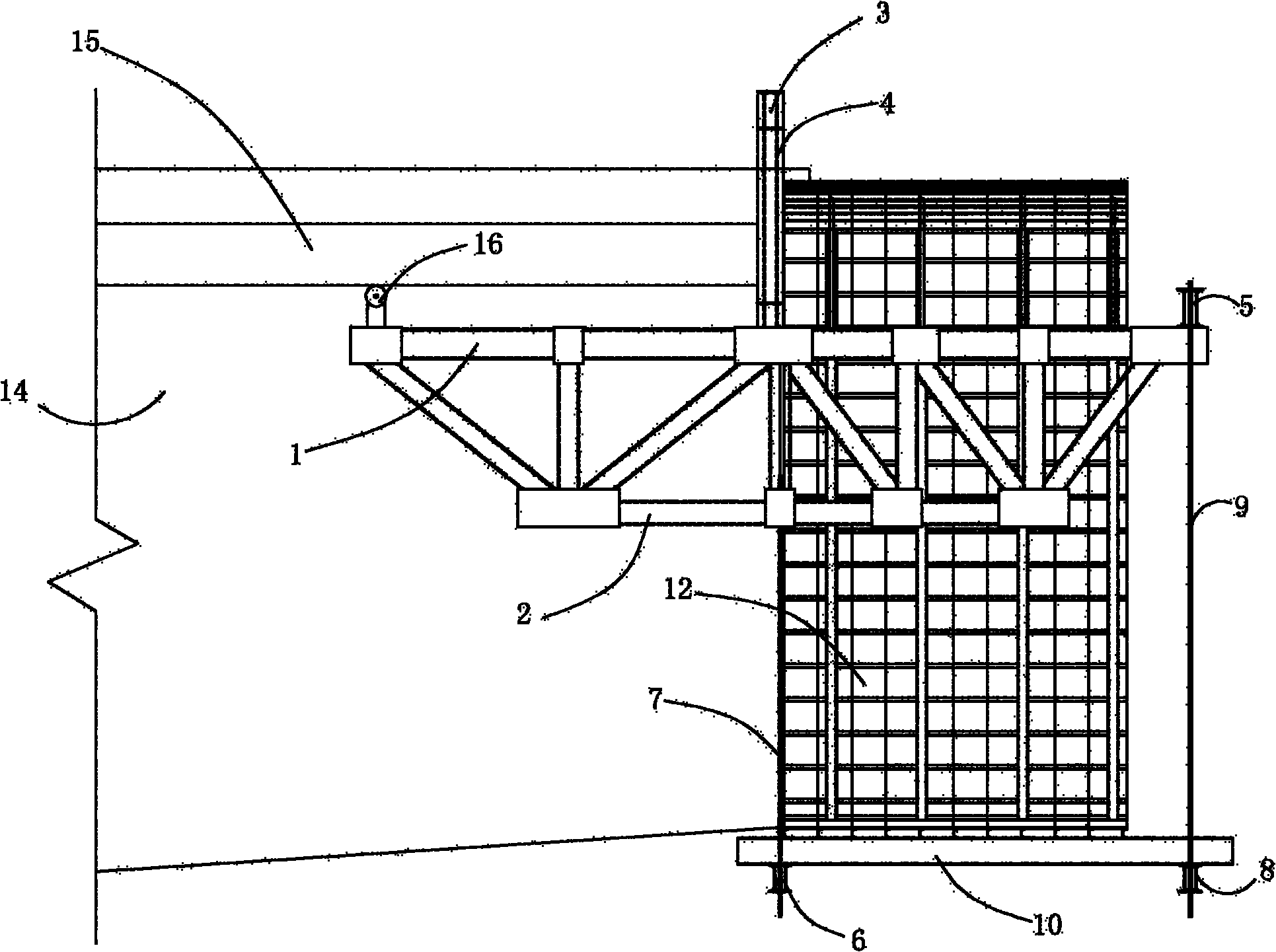
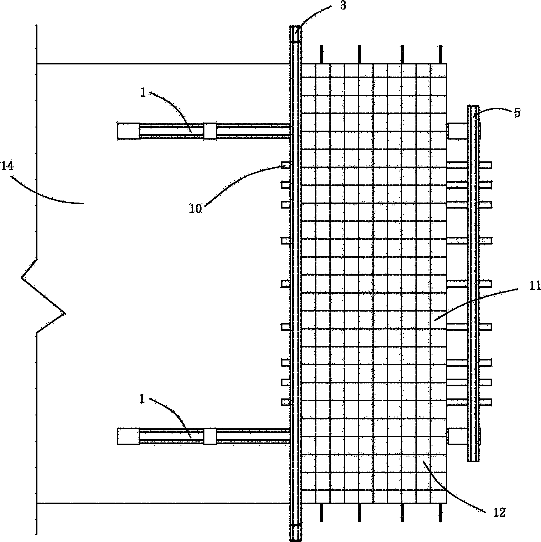
[0031] see figure 1 , figure 2 and image 3 , the structural form of the lower bearing hanging basket in the present embodiment is:

[0032] The under-supporting hanging basket in the bridge construction in this embodiment has two pieces of inverted trapezoidal main trusses, which are composed of upper chord 1, lower chord 2, vertical and oblique rods connected between upper chord 1 and lower chord 2 ; Between the afterbody of the upper chord 1 and the bottom surface of the poured beam section box girder flange 15, the upper chord jacking jack is set, and a pair of walking wheels 16 with the bottom surface of the box girder flange as the supporting surface are set; The rear upper boom 4 is set between the middle part and the rear upper beam 3; the front end of the upper chord 1 is connected with the front upper beam 5; the rear lower boom 7 is set between the middle part of the lower chord 2 and the rear lower beam 6; 5 is connected with the front suspension rod 9 between ...


PUM


Abstract

The invention discloses a lower supported hanging basket in bridge construction and application thereof. The invention is characterized in that: the lower supported hanging basket is provided with two primary trusses having inverted trapezoidal structures, and an upper chord shoring jack is arranged between the tail of an upper chord and the bottom surface of a box girder edge board; an upper rear suspender is arranged between the middle of the upper chord and an upper rear crossbeam; the front end of the upper chord is connected with an upper front crossbeam; a lower rear suspender is arranged between the middle of a lower chord and a lower rear crossbeam; the upper front crossbeam is connected with a lower front crossbeam through a front suspender; parallelly arranged bottom basket longitudinal beams are fixedly connected between the lower front crossbeam and the lower rear crossbeam; and a hanging basket bottom die is fixedly arranged on the bottom basket longitudinal beams, and hanging basket side dies are positioned on the inner side of the two primary trusses. The hanging basket travelling mode is improved, a bound framework of steel reinforcement can be integrally hoisted into a bottom die platform space and directly subjected to concreting operation, and the construction period is shortened.

Description

technical field [0001] The invention relates to a hanging basket structure in bridge construction and its application. Background technique [0002] In bridge construction, the hanging basket is a cantilever cast-in-place device for large-span concrete bridges with traffic requirements and poor foundation conditions. [0003] Currently commonly used hanging basket structures include top-loading triangular hanging baskets, diamond-shaped hanging baskets, bowstring hanging baskets and hybrid hanging baskets, etc. These existing hanging baskets are all arranged on the top of the beam body. The concrete pouring state of various hanging baskets is similar to the stress mode in the walking state of the hanging basket. In order to ensure the stability of the hanging basket during construction, the finished rolled rebar must be pre-embedded on the poured beam body as the rear anchor or loading balance weight. . It is necessary to set the anti-tension support, glide slope and glide...

Claims


Application Information

Patent Timeline
IPC IPC(8): E01D21/00E01D21/10
Inventor 梁超张宏斌李彬李波杨真
Owner THE FIRST ENG CO LTD OF CTCE GRP
Learn More