
Ice crystal evaporator and ice crystal water cooling device producing from same

An evaporator, water cooling technology, applied in the direction of evaporator/condenser, refrigerator, refrigeration components, etc., can solve the problems of low heat exchange energy efficiency, difficult to widely use, large device volume, etc., to achieve rapid cooling, High cooling efficiency and small volume

Active Publication Date: 2012-12-26
蒋军闽
View PDF0 Cites 0 Cited by
  • Summary
  • Abstract
  • Description
  • Claims
  • Application Information

AI Technical Summary

Problems solved by technology

There are three sources of this water: one is directly obtained by dissolving ice; the second is to use a salt water tank device of tens of tons, and water tanks ranging from tens of tons are placed in the tank at the same time. The antifreeze performance of salt water, through a refrigeration cycle system, the temperature of the salt water is reduced to about -20 degrees, and then the temperature in the water tank is reduced to about zero degrees through the heat exchange between the salt water and the water tank. This device is currently widely used in the seafood quick-freezing industry or large-scale lettuce In the manufacturing market, this method has made great progress compared to the method of directly using ice to melt, but the energy efficiency of heat exchange is still not high, the volume of the device is large, and the manufacturing cost is high, so it is difficult to be widely used; the third is The national standard evaporator is used for refrigeration, and its general structure can be found in Figure 5 : Including a shell 90, one end of the shell 90 is provided with a refrigerant medium liquid inlet chamber and a refrigerant medium return air chamber separated by a partition, and a refrigerant medium return chamber is arranged at the other end of the housing 90, and the liquid inlet chamber and the air outlet chamber Evenly distributed cooling copper tubes 94 are arranged in the housing 90 between the return chamber and the cavity between the inner wall of the housing 90 and the cooling copper tubes 94, and several partitions 93 are arranged perpendicular to the axis of the cooling copper tubes 94 There are flow openings 97 at different angles on the outside of each partition 93, so that the flow direction of the cooled medium is to enter from the water inlet 91 on the housing wall at the right end of the cooling copper pipe 94, and then pass through each The flow opening 97 on the dividing plate 93 flows out from the water outlet 92 on the housing wall at the left end of the cooling copper pipe 94, and the cooling medium passes through the liquid inlet chamber, the copper pipe 94, the return chamber, the copper pipe successively from the liquid inlet 95. Pipe 94 and air outlet cavity are drawn out from the air return port 96 as gas. The disadvantages are: one is that the cooled medium (water) flows from one end of the cooling copper tube to the other end, due to the low temperature of the cooling medium The flow rate of the refrigerated medium is slow when passing through, which will easily cause the refrigerated medium to freeze and block the passage of the refrigerated medium, causing the evaporator to fail due to the inability to cool within a certain period of time. In this case, the machine must be shut down to remove ice If it is turned on again, it will cause the evaporator shell and the internal cooling copper pipe to burst in serious cases, which will affect the cooling needs at that time and increase the purchase cost of the equipment; device with the same faults and inconveniences

Method used


Image

  • Ice crystal evaporator and ice crystal water cooling device producing from same
  • Ice crystal evaporator and ice crystal water cooling device producing from same
  • Ice crystal evaporator and ice crystal water cooling device producing from same

Examples


Embodiment Construction

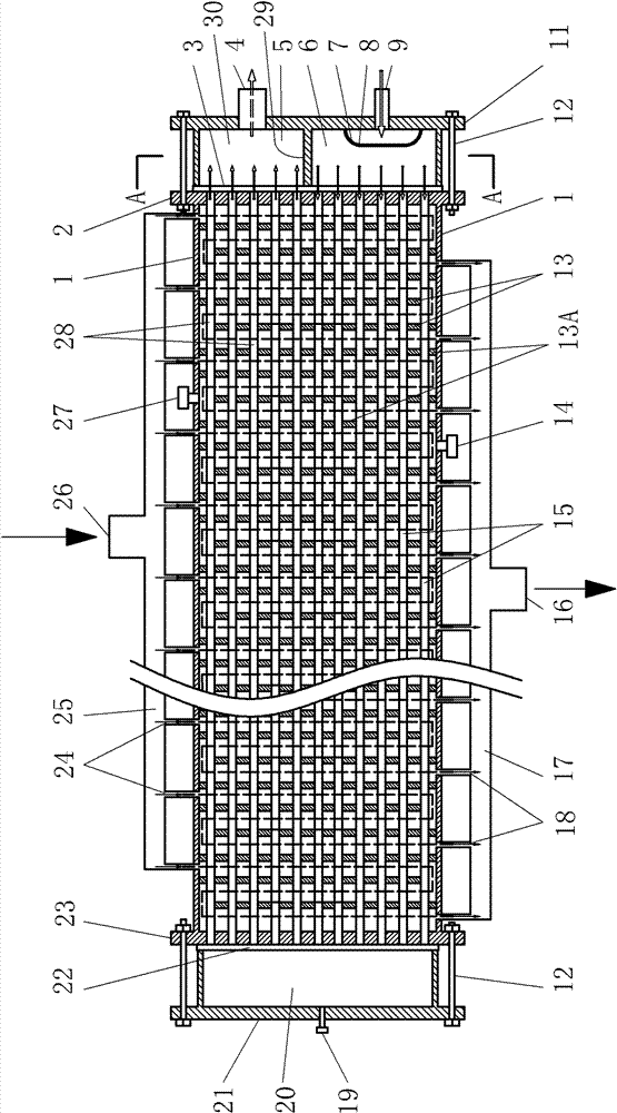
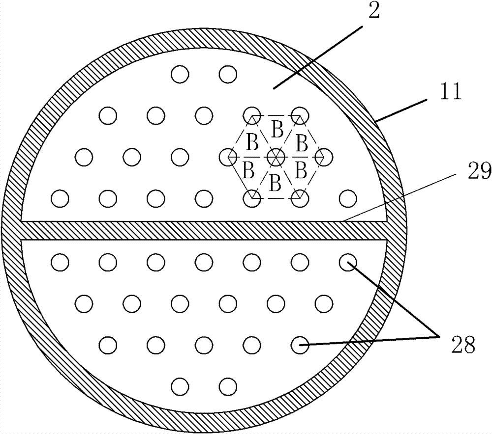
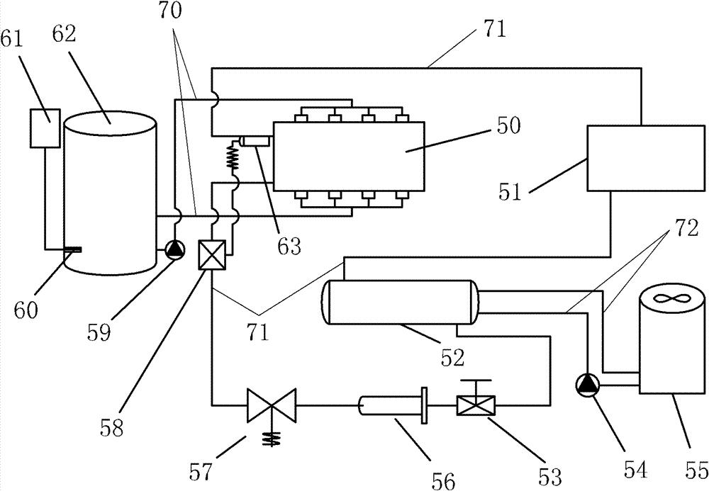
[0024] Below in conjunction with accompanying drawing, the present invention will be further described with specific embodiment, see Figure 1-4 :

[0025] The ice crystal evaporator is provided with left and right positioning end caps 23, 2 respectively at both ends of the tubular shell 1, and the left and right positioning end caps 23, 2 are correspondingly provided with evenly distributed round holes, and the tubular shell 1 The two ends of the inner evaporating tube 28 are installed on the round holes on the left and right positioning end caps 23 and 2. The outside of the left positioning end cap 23 is sealed with a return cover 21 to form a return cavity 20, and the outside of the right positioning end cap 2 The liquid inlet and air return cover 11 is sealed and connected, and the chamber provided between the liquid inlet and air return cover 11 and the right positioning end cover 2 is divided into a liquid inlet chamber 6 and an air return chamber 30 by a central partiti...


PUM


Abstract

The invention relates to an ice crystal evaporator and an ice crystal water cooling device producing from the same, belonging to the technical field of refrigeration. The ice crystal evaporator is characterized in that a liquid inlet channel is formed by an evaporator tube, a liquid inlet and a liquid outlet in a tubular casing; and the outer channel of the evaporator tube of the tubular casing is divided into more than one S-shaped channel forming a water return channel through a water inlet of a water divider and a water outlet of a water collector. The ice crystal water cooling device is characterized in that the return air inlet of the ice crystal evaporator is communicated with a compressor, a condenser, a liquid feeding valve, a dry filter, a liquid feeding electromagnetic valve and a thermostatic expansion valve in sequence, and then is communicated with the liquid inlet of the ice crystal evaporator; a cooling water inlet / outlet of the condenser is connected with a cooling tower in series; and a water inlet / outlet of the ice crystal evaporator is communicated with a water circulating pump and an ice crystal energy storage tank in series. The invention has the advantages of high cooling efficiency, no icing and low cooling temperature and is suitable for production of energy storage central air-conditioning, marine fishing, seafood processing, fruit, vegetable or meat processing, and the like; the cooled medium is municipal water.

Description

technical field [0001] The invention belongs to the technical field of refrigeration, in particular to an ice crystal evaporator and an ice crystal water refrigeration device made of the ice crystal evaporator. Background technique [0002] At present, a kind of quick-freezing fresh-keeping treatment method is used many times in the ocean fishing chilling process, seafood processing, vegetables and fruits or frozen meat food processing technology. This process is to soak the product to be processed in water, and then put it in Quick-freezing is performed in an ultra-low temperature environment, so that an ice layer is formed on the surface of the product to achieve the purpose of freshness preservation. In consideration of efficiency, the water used for soaking is zero-degree or below-zero water. There are three sources of this water: one is directly obtained by dissolving ice; the second is to use a salt water tank device of tens of tons, and water tanks ranging from tens o...

Claims


Application Information

Patent Timeline
Patent Type & Authority Patents(China)
IPC IPC(8): F25B39/02F25C1/00
Inventor 洪志文
Owner 蒋军闽
Learn More