
Transformer system current phasor test system and method based on low frequency excitation response

A technology of system current and low-frequency excitation, which is applied in the direction of transformer testing, etc., can solve the problems that the transformer cannot carry out primary current flow, and cannot pass current to verify the correctness of the differential protection circuit, so as to achieve intuitive and clear setting of CT polarity correctness criteria , Reduce the volume and weight of the equipment, and the effect of short flow time

Active Publication Date: 2022-03-08
STATE GRID FUJIAN ELECTRIC POWER CO LTD +2
View PDF6 Cites 0 Cited by
  • Summary
  • Abstract
  • Description
  • Claims
  • Application Information

AI Technical Summary

Problems solved by technology

[0004] In view of this, the purpose of the present invention is to provide a transformer system current phasor test method based on low-frequency excitation response, which effectively solves the problem that the transformer cannot carry out primary current flow, and can solve the problem of transformer differential protection under static conditions using bushing CT. Unable to verify the correctness of the differential protection circuit through flow

Method used


Image

  • Transformer system current phasor test system and method based on low frequency excitation response
  • Transformer system current phasor test system and method based on low frequency excitation response
  • Transformer system current phasor test system and method based on low frequency excitation response

Examples


Embodiment Construction

[0038] The invention will be further described below with reference to the accompanying drawings and examples.

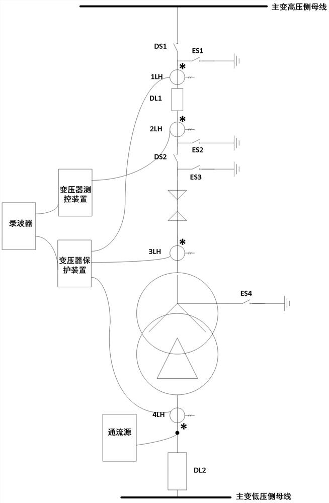
[0039] Please refer to figure 1 The present invention provides a transformer system current-phase quantity test system based on a low-frequency excitation response, including a flow source, a hhotoscope, a transformer high pressure side unit, a transformer unit, and a transformer low pressure side unit; the transformer high pressure side unit is high pressure by the transformer. Side bus bar side isolation cutter DS1, transformer high pressure side outline side isolation cutter DS2, transformer high pressure side circuit breaker DL1, bus side three-phase joint knife gate ES1, outline side three-phase joint tool gate ES2, main transformation high pressure side ground The cutter ES3, the main transformer high-pressure side protection grade current transformer 1LH, the main transformer high voltage side measures the level current transformer 2LH; the transformer unit uses ...


PUM


Abstract

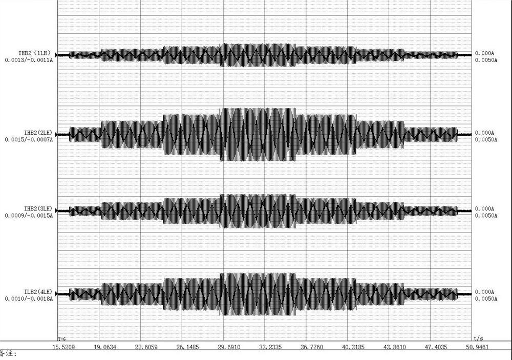
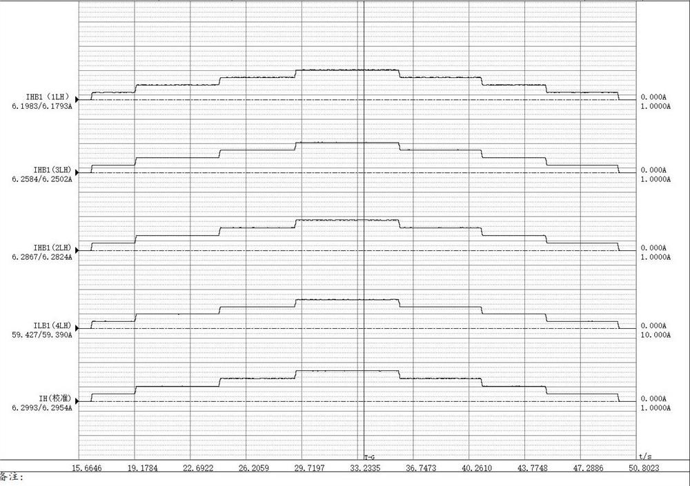
The invention discloses a current phasor test method of a transformer system based on low-frequency excitation response, which includes short-circuiting the three-phase grounding of the high-voltage side of the transformer, applying a low-frequency steady-state current of 10-25 Hz between phases at the low-voltage side of the transformer, and recording the transformer with a wave recorder. High and low voltage side related protection, measurement and control and other secondary equipment current, through waveform data analysis, determine the phasor information such as current amplitude and phase, and then judge the correctness of the polarity and transformation ratio of the current transformer. The invention reduces the test capacity requirements of the flow-through equipment, effectively solves the problem that the transformer cannot carry out one-time flow-through, and can solve the problem that the differential protection of the transformer using bushing CT cannot pass flow to verify the correctness of the differential protection circuit under static conditions. The transformer no-load phasor test provides a solution, saves the time and cost of power transmission debugging, does not need to disconnect the main wiring once, the test wiring is convenient, the waveform analysis frequency adaptability is good, the flow time is short, safe and reliable, and the accuracy is high.

Description

Technical field [0001] The present invention belongs to the field of power debugging and power test, and is specifically related to a transformer system current-phase amount test method based on a low-frequency excitation response. Background technique [0002] In order to systematically check the correctness of a dual-equipment current sampling system before starting power generation, the site usually carries a flow test to the switch, busbar and other equipment, especially for the high-pressure start-up transformer in the power plant, due to the electric power supply In the commissioning phase, the construction and installation progress of the factory is often lagged behind. Many downstream load equipment do not have power-saving conditions. It is difficult to organize enough loads to carry out protective belt load phases testing, and cannot ensure that transformer protection is 100% correctly. It affects the safety and stable operation of the transformer, so it is necessary to...

Claims


Application Information

Patent Timeline
Patent Type & Authority Patents(China)
IPC IPC(8): G01R31/62
Inventor 施晟石吉银林志坚肖世挺卢万华施清山王晓东曾天发
Owner STATE GRID FUJIAN ELECTRIC POWER CO LTD
Learn More