Supercharge Your Innovation With Domain-Expert AI Agents!

Method for measuring near-wall electroosmosis rate of micro channel

A technology of electroosmotic velocity and measurement method, which is applied in the direction of radio wave measurement system, electromagnetic wave reradiation, and the use of devices for measuring the time required to move a certain distance, etc., which can solve the problem of not being able to obtain the flow velocity distribution of the main body of electroosmotic flow

Inactive Publication Date: 2011-06-15
大连市第三人民医院
View PDF0 Cites 0 Cited by
  • Summary
  • Abstract
  • Description
  • Claims
  • Application Information

AI Technical Summary

Problems solved by technology

However, only the evanescent field excitation can only measure the flow field within about 100nm from the wall, and the main flow velocity distribution of the electroosmotic flow cannot be obtained. Simultaneous measurement of the flow velocity near the wall and the main flow velocity can more directly measure the electroosmotic flow. type to measure

Method used


Image

  • Method for measuring near-wall electroosmosis rate of micro channel
  • Method for measuring near-wall electroosmosis rate of micro channel
  • Method for measuring near-wall electroosmosis rate of micro channel

Examples


Embodiment Construction

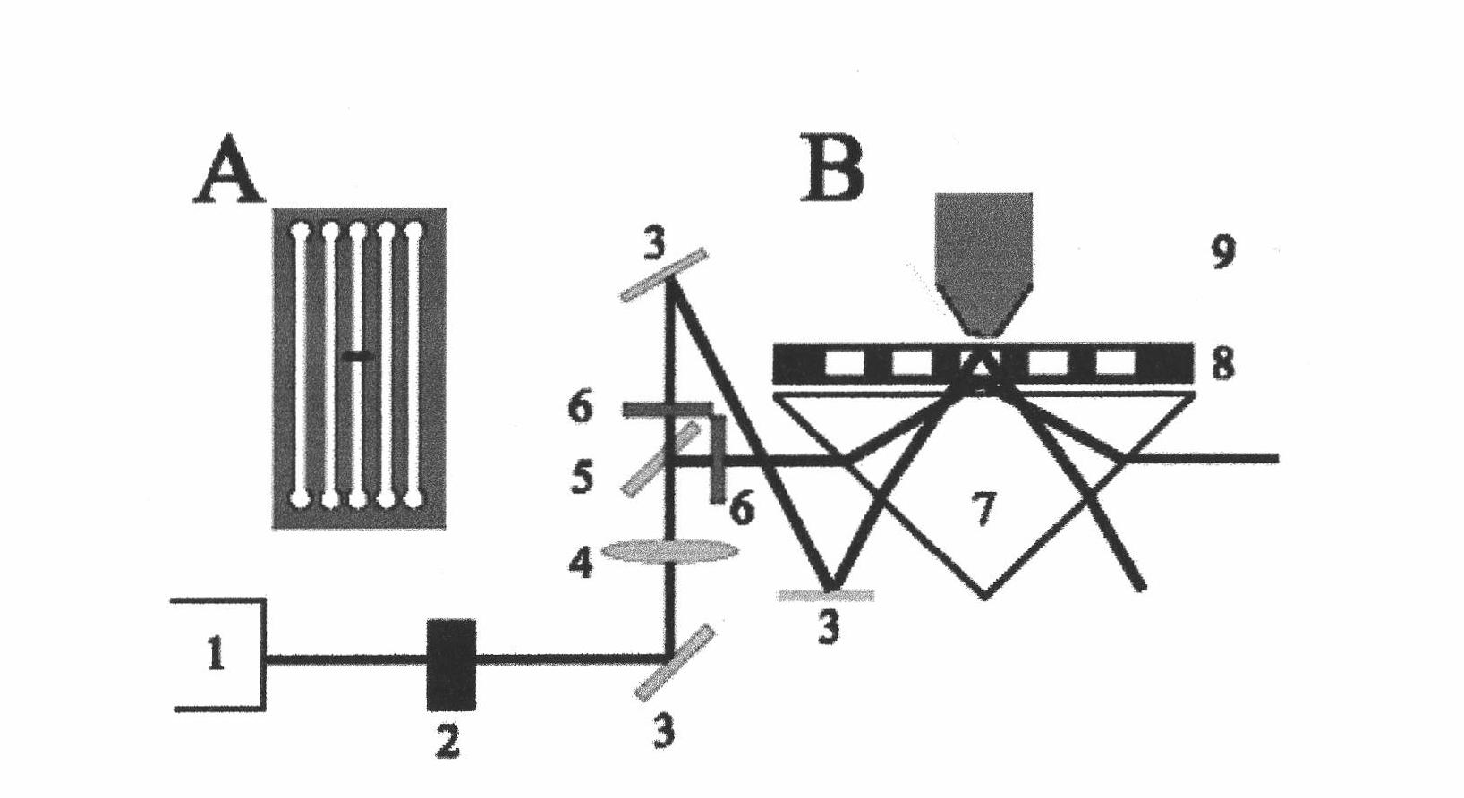
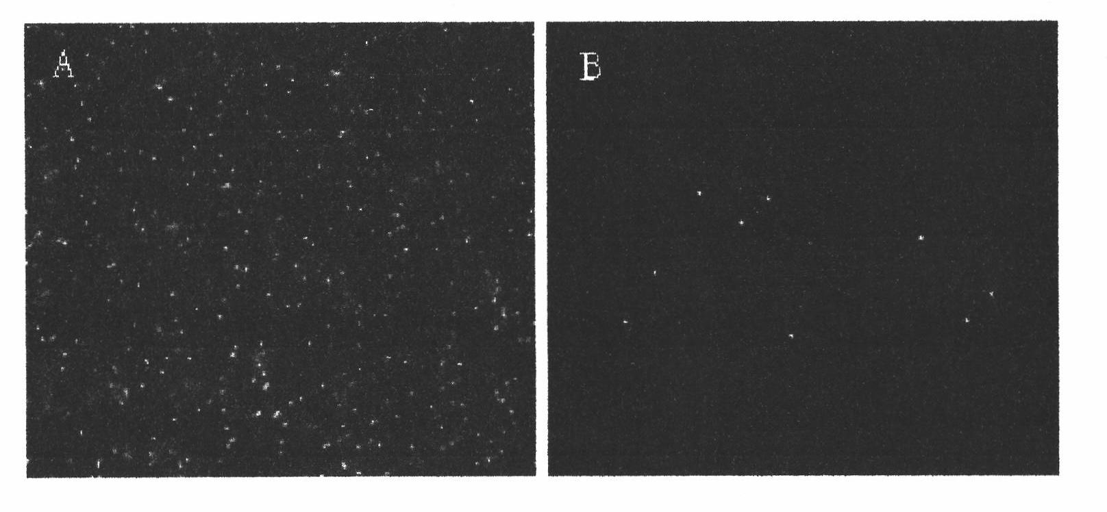
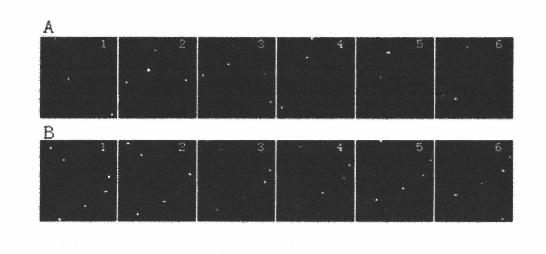
[0025] Fluorescent microspheres (3×10 8 beads / mL) solution was diluted five-fold and fifty-fold with 25 mM NaAC buffer (pH=8) for evanescent-field and wide-field imaging, respectively. During the experiment, add NaAC buffer solution to one buffer pool of the microchannel, wait until it is full of the channel, add the fluorescent bead solution or DNA solution to another buffer pool, keep the liquid level at both ends of the channel even, Applying a voltage drives the microspheres and lambda DNA molecules through the detection zone. First, the evanescent field is used to excite, and the flow velocity near the wall is collected, and then the shading plate standing on the vertical optical path is removed (see figure 1 B), Acquisition of bulk flow velocity images under widefield excitation. The electric field intensity used in the experiment is relatively low to reduce the electrophoretic velocity of the fluorescent microspheres and λDNA molecules, so as to truly reflect the flow...


PUM


Abstract

The invention provides a method for measuring the near-wall electroosmosis rate of a micro channel, which is characterized in that: an optical path capable of forming an evanescent field excitation mode and a wide field excitation mode simultaneously is constructed, wherein a prism (7) is taken as an object substrate, the micro channel (8) is coupled on the prism, and the excitation modes are switched by changing the position of a light shielding plate (6). The method comprises the following steps of: injecting a sample into the micro channel, applying voltage to the two ends of the channel, continuously acquiring fluorescent signals of fluorescent microspheres in the given time interval, and calculating a ratio of displacement to the time interval to obtain the migration rate of the microspheres, namely the flow rate of fluid. When the evanescent field excitation mode is adopted, near-wall flow rate can be obtained; and when the wide field excitation mode is adopted, main flow rate can be obtained.

Description

technical field [0001] The invention mainly relates to a method for simultaneously measuring the main body flow velocity and near-wall flow velocity of an electroosmotic flow in a microchannel. Background technique [0002] Under the action of an external electric field, the liquid in the microchannel or capillary moves relative to the tube wall to form electroosmotic flow. The thickness of the electric double layer formed by the solid-liquid interface is usually only 0.1nm-10nm (corresponding to the electrolyte solution concentration of 1M-10 -4 M). Outside the electric double layer, the velocity distribution of electroosmotic flow is uniform, and the velocity at each point is equal, which is an important reason why electroosmotic drive plays a dominant role in biochemical separation analysis. [0003] There have been extensive mathematical and simulation studies of fluid flow patterns in fully developed electroosmotic flows, such as those between parallel plates, and in ...

Claims


Application Information

Patent Timeline
IPC IPC(8): G01P3/68
Inventor 董秀玲
Owner 大连市第三人民医院
Features
  • R&D
  • Intellectual Property
  • Life Sciences
  • Materials
  • Tech Scout
  • Unparalleled Data Quality
  • Higher Quality Content
  • 60% Fewer Hallucinations
Learn More