Combustor capable of quickly realizing flameless combustion

A flameless combustion and burner technology, which is applied to gas fuel burners, burners, combustion types, etc., can solve the problems of scouring furnace walls, furnace erosion damage, lack of flame stabilizing devices, etc., to achieve stable and easy combustion process. The effect of maintenance and quick switching

Active Publication Date: 2015-10-21
PEKING UNIV
View PDF8 Cites 6 Cited by
  • Summary
  • Abstract
  • Description
  • Claims
  • Application Information

AI Technical Summary

Problems solved by technology

However, due to the lack of a flame stabilizing device, the invention cannot heat at the rated power during the preheating furnace stage, and can only gradually increase the flow of gas and air to avoid the flameout problem by gradually heating
Due to the partial premixing method in the preheating furnace stage, there will be hidden

Method used


Image

  • Combustor capable of quickly realizing flameless combustion
  • Combustor capable of quickly realizing flameless combustion
  • Combustor capable of quickly realizing flameless combustion

Examples


Embodiment Construction

[0016] The present invention will be described in detail below in conjunction with the accompanying drawings and embodiments.

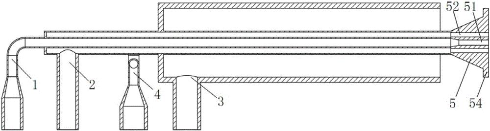
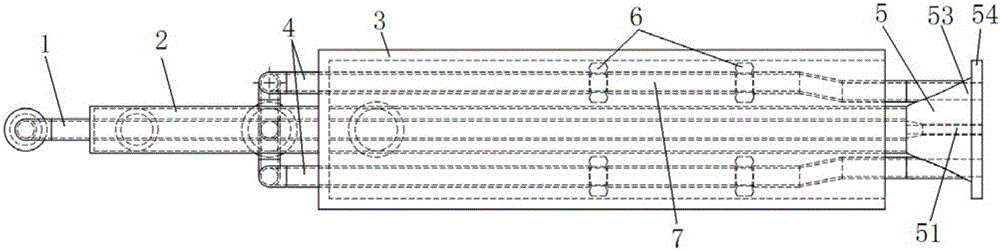
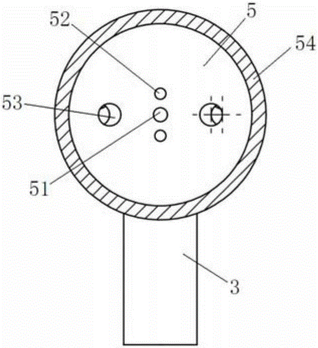
[0017] Such as Figure 1~3 As shown, the present invention includes a central gas nozzle 1, a loop gas nozzle 2 is arranged coaxially outside the center gas nozzle 1, and a loop air nozzle is coaxially arranged outside the loop gas nozzle 2. Pipe 3, two symmetrical air nozzles 4 are arranged parallel and symmetrically on both sides of the loop gas nozzle 2, and the two symmetrical air nozzles 4 are located between the inner wall of the loop air nozzle 3 and the outer wall of the loop gas nozzle 2. The front ends of the central gas nozzle 1 and the loop gas nozzle 2 are jointly connected with a flame-stabilizing blunt body 5, and the flame-stabilizing blunt body 5 is connected with the central gas nozzle 1 and the loop gas nozzle 2 in a detachable manner, such as threaded connection, snap connection, etc. A central gas nozzle 51, more than two periph...


PUM


Abstract

The invention relates to a combustor capable of quickly realizing flameless combustion. The combustor comprises a center fuel gas spraying pipe, a loop fuel gas spraying pipe coaxially sealed outside the center fuel gas spraying pipe, two symmetric air spraying pipes symmetrically arranged at the two sides of the loop fuel gas spraying pipe in parallel, a loop air spraying pipe arranged outside the loop fuel gas spraying pipe and the symmetric air spraying pipe, and a flame stabilizing blunt body, wherein the loop air spraying pipe and the loop fuel gas spraying pipe are coaxially arranged; the flame stabilizing blunt body is detachably connected to the front ends of the center fuel gas spraying pipe and the loop fuel gas spraying pipe, and is provided with a center fuel gas nozzle communicated with the center fuel gas spraying pipe, more than two peripheral fuel gas nozzles positioned around the center fuel gas nozzle and communicated with the loop fuel gas spraying pipe and two air nozzles symmetrically arranged at the two sides of the center fuel gas nozzle; the two air nozzles are communicated with the two symmetric air spraying pipes; an annular projection is arranged at the front end of the flame stabilizing blunt body; the outer diameter of the annular projection is equal to the inner diameter of the loop air spraying pipe; and a distance is left between the annular projection and the front end of the loop air spraying pipe.

Description

technical field [0001] The invention relates to a burner, in particular to a burner capable of quickly realizing flameless combustion. Background technique [0002] Flameless combustion (MILD combustion, Flameless combustion) is a new type of clean combustion technology. This technology is realized by controlling the rapid mixing of fuel, oxidant and high-temperature flue gas in a furnace with low oxygen concentration and temperature higher than the self-ignition point of fuel. Compared with traditional combustion methods, flameless combustion has no visible flame front, and the temperature and brightness of the entire furnace are uniform, avoiding a large amount of NO x At the same time, the efficiency of thermal radiation and heat exchange is improved, and the combustion is stable and the noise is extremely low. It is regarded as one of the most potential clean combustion technologies by the international combustion community. At present, air pollution is becoming more a...

Claims


Application Information

Patent Timeline
IPC IPC(8): F23D14/12F23D14/26F23D14/46
CPCF23D14/22F23D14/26F23D14/46
Inventor 米建春张健鹏
Owner PEKING UNIV
Why Eureka
Try Eureka