Ultrasonic wave wind speed and wind direction measuring device of wind generating set

A technology for wind turbines and wind speed and direction, which is applied in measurement devices, fluid velocity measurement, velocity/acceleration/impact measurement, etc., can solve problems such as cumbersome maintenance, inconvenient maintenance lines, waste of human resources and costs, and achieve low energy consumption. , easy maintenance, simple installation effect

Inactive Publication Date: 2012-07-11
UNIV OF ELECTRONICS SCI & TECH OF CHINA
View PDF0 Cites 0 Cited by
  • Summary
  • Abstract
  • Description
  • Claims
  • Application Information

AI Technical Summary

Problems solved by technology

[0003] The communication between the ultrasonic anemometer and the wind turbine and the power supply of the ultrasonic anemometer itself in the ultrasonic wind speed and direction measuring device of the wind power generating set are all realized through cables, which poses a challenge to the maintenance and replacement of the cables. Higher requirements, and with the large amount of domestic wind power generation put into operation, such maintenance is quite cumbersome, which has caused a great waste of human resources and costs, especially when the erection point of the ultrasonic anemometer and the wind turbine cabin controller It is more inconvenient to lay and maintain lines when the distance is large

Method used


Image

  • Ultrasonic wave wind speed and wind direction measuring device of wind generating set
  • Ultrasonic wave wind speed and wind direction measuring device of wind generating set
  • Ultrasonic wave wind speed and wind direction measuring device of wind generating set

Examples


Embodiment

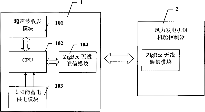
[0022] figure 1 It is a principle block diagram of a specific embodiment of an ultrasonic wind speed and direction measuring device for a wind power generating set of the present invention.

[0023] Such as figure 1 As shown, in this embodiment, the ultrasonic wind speed and direction measurement device for a wind power generating set includes two parts: an ultrasonic anemometer 1 and a nacelle controller 2 for a wind generating set.

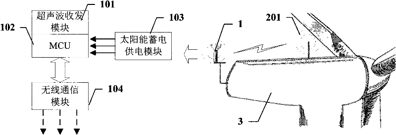
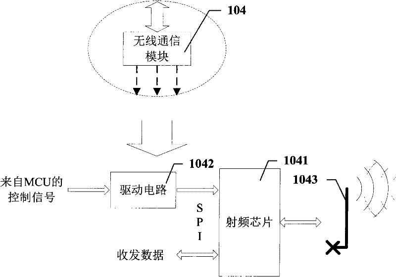
[0024] The ultrasonic anemometer 1 includes an ultrasonic transceiver module 101 , a central control unit 102 , a solar energy storage power supply module 103 and a ZigBee wireless communication module 104 . The nacelle controller 2 of the wind power generating set also has a ZigBee wireless communication module, which enables it to have a ZigBee wireless communication function, and can communicate wirelessly with the ultrasonic anemometer 1 .

[0025] The ultrasonic transceiver module 101 collects the wind speed and direction under the contro...


PUM


Abstract

The invention discloses an ultrasonic wave wind speed and wind direction measuring device of a wind generating set, comprising an ultrasonic wave wind speed and wind direction meter and a wind generating set cabin controller, wherein the ultrasonic wave wind speed and wind direction meter comprises an ultrasonic wave transceiver module, a central control unit, a solar energy accumulation power supply module and a ZigBee wireless communication module; the ultrasonic wave transceiver module collects the wind speed and the wind direction under the control of the central control unit; the collected wind speed and wind direction data is sent to the wind generating set cabin controller via the ZigBee wireless communication module so as to control the wind generating set; the solar energy accumulation power supply module supplies power for the whole ultrasonic wave wind speed and wind direction meter by utilizing generated electrical energy; and wireless communication and the solar energy accumulation power supply module are used for respectively realizing communication and automatic power supply. The ultrasonic wave wind speed and wind direction measuring device has the characteristics of low energy consumption and the like, is simple to install and simple and convenient to maintain, is especially suitable for field situations with severe environment and difficult construction maintenance, and communication power supply circuits do not need to be laid.

Description

technical field [0001] The invention belongs to the technical field of wind power generation, and more specifically relates to an ultrasonic wind speed and direction measurement device for a wind power generating set. Background technique [0002] Wind speed and direction measurement is widely used in industrial production and scientific experiments. The common wind cup type and wind vane type anemometer due to the inherent defects of its own mechanical structure, the sensitivity is not high when measuring low wind speed, and it will age to a certain extent with the increase of use time. The measurement accuracy and use in harsh working environments Life expectancy is greatly affected. Since most wind turbines work in areas with relatively harsh environments and the control of the unit has high requirements for the accuracy of wind speed and wind direction data, the ultrasonic anemometer has no mechanical wear, high measurement accuracy, high sensitivity, and good stability...

Claims


Application Information

Patent Timeline
Patent Type & Authority Patents(China)
IPC IPC(8): G01P5/24G01P13/02H04L7/04
Inventor 邹见效徐红兵彭超
Owner UNIV OF ELECTRONICS SCI & TECH OF CHINA
Why Eureka
Try Eureka