
Phase test device and control method thereof

A control method and phase estimation technology, which are applied in the measurement device, the measurement of electrical variables, the phase angle between voltage and current, etc., can solve the problems of deviation of measurement results, consumption of many sampling points, inapplicability, etc., and achieve reduced interference. , reducing cost and complexity requirements, the effect of high noise immunity

Inactive Publication Date: 2011-06-15
TIANJIN UNIV
View PDF6 Cites 15 Cited by
  • Summary
  • Abstract
  • Description
  • Claims
  • Application Information

AI Technical Summary

Problems solved by technology

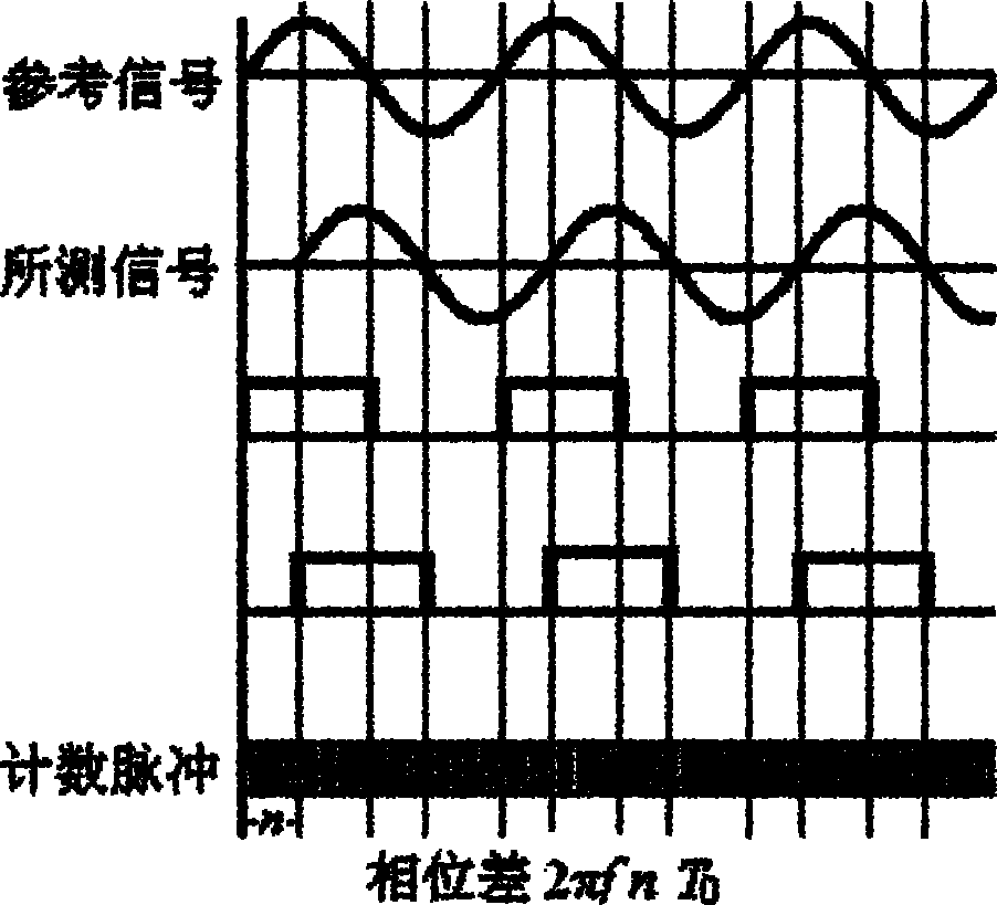
It can be seen that the disadvantages of this method are: (a) a reference sine wave needs to be generated, and the frequency of the reference signal is required to be exactly the same as that of the measured sine signal. If there is a slight deviation, it will bring serious deviations to the measurement results ; (b) The pulse counting signal needs to be specially generated, and the measurement accuracy largely depends on the basic pulse width T 0 , only by reducing T 0 In order to improve the measurement accuracy, this requires high hardware equipment
[0019] However, through experiments and theory, it can be proved that various phase estimation methods based on DFT spectrum correction have the following defects: when these DFT spectrum correction methods estimate the phase, they all follow the steps of first estimating the frequency, obtaining the frequency deviation value, and then performing phase estimation. is carried out, so this will directly bring the error of the frequency estimation into the phase estimation
However, literature [21, 22] pointed out that an N-order all-phase FFT needs to consume 2N-1 input samples to obtain the instantaneous phase estimation of the center sample.
Therefore, although the all-phase FFT has high precision, it consumes a little more samples, and it is not suitable for phase measurement of short-sample low-frequency signals.

Method used


Image

  • Phase test device and control method thereof
  • Phase test device and control method thereof
  • Phase test device and control method thereof

Examples


Embodiment Construction

[0078] In order to make the object, technical solution and advantages of the present invention clearer, the implementation manner of the present invention will be further described in detail below in conjunction with the accompanying drawings.

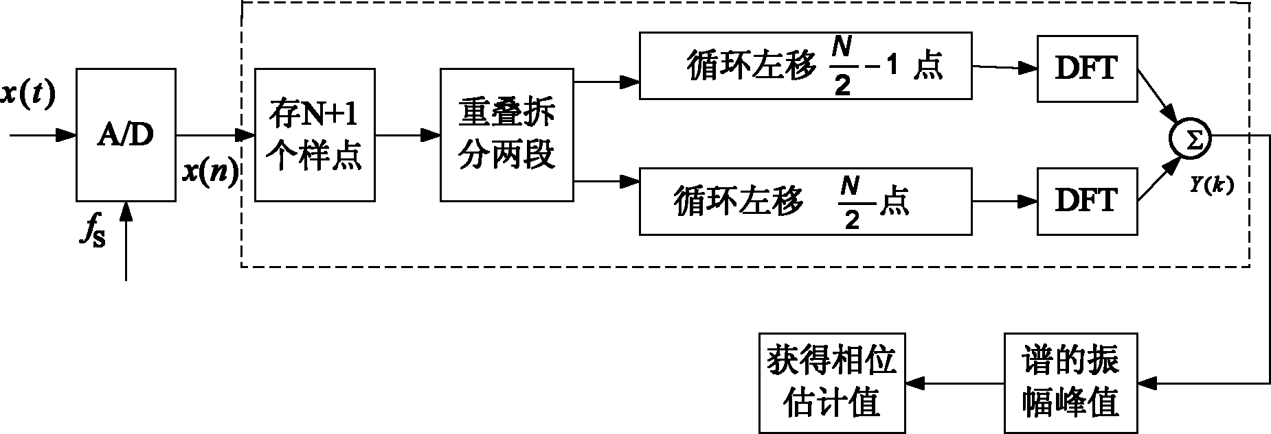
[0079] In order to achieve accurate estimation of the instantaneous phase of the central sample point with fewer sample points, reduce computational complexity, and expand the scope of application, an embodiment of the present invention provides a phase measurement device, see figure 2 , see the description below:

[0080] The phase measuring device includes: a conditioning circuit, an A / D converter, a digital signal processor, an output driver and a display module thereof,

[0081] The analog signal is connected to the conditioning circuit. The conditioning circuit adjusts the amplitude of the analog signal according to the first threshold to obtain the first analog signal. The first analog signal is sampled by the A / D converter to o...


PUM


Abstract

The invention discloses a phase test device and a control method thereof, and relates to the technical field of digital signal processing. The phase test device comprises a conditioning circuit, an A / D converter, a digital signal processor, an output driver and a display circuit of the output driver, wherein an analog signal is accessed to the conditioning circuit, the conditioning circuit adjusts the amplitude of the analog signal according to a first threshold to obtain a first analog signal, the first analog signal is sampled by the A / D converter to obtain a sample sequence, the sample sequence is accessed into the digital signal processor through a parallel digital input manner, an estimated phase value of the sample sequence is obtained through processing of the digital signal processor, and the estimated phase value of the sample sequence is output and displayed by the output driver and the display circuit of the output driver. The phase test device can realize accurate estimation of instantaneous phase of the center sample point by using shorter sample data; the phase test device can realize phase estimation without frequency estimation; without frequency estimation, error of frequency estimation is avoided, the cost of hardware and the requirement on complexity are reduced, and the requirements in actual application are met.

Description

technical field [0001] The invention relates to the technical field of digital signal processing, in particular to a phase measuring device and a control method thereof. Background technique [0002] In engineering fields such as communications, instrumentation, electric power, optical applications, and fault diagnosis, there are a large number of high-precision, efficient, and fast estimation problems for the phase of signals. For example, in a communication system using QAM and PSK modulation, only by quickly estimating the initial phase of the carrier in each symbol period at the receiving end can the constellation diagram be correctly restored and correct decoding be realized [1] ; Among all kinds of instruments, the phase meter is a common one. The basic function of the phase meter is to accurately measure and calculate the phase of the signal at each moment [2] ; and in the case of grid-connected closing of the power system, it is required to accurately measure the ph...

Claims


Application Information

Patent Timeline
Patent Type & Authority Applications(China)
IPC IPC(8): G01R25/00
Inventor 黄翔东王兆华
Owner TIANJIN UNIV
Learn More