
Exposure lighting set and exposure machine

An exposure lamp and exposure machine technology, applied in the field of exposure machines, can solve the problem of inability to reduce the temperature of an infrared cut-off filter, and achieve the effect of taking away quickly

Active Publication Date: 2012-05-23
AU OPTRONICS CORP
View PDF0 Cites 0 Cited by
  • Summary
  • Abstract
  • Description
  • Claims
  • Application Information

AI Technical Summary

Problems solved by technology

[0004] However, for high-power lamps, although users have already used water cooling to cool them, they still cannot reduce the temperature of the infrared cut filter to the ideal temperature in many cases.

Method used


Image

  • Exposure lighting set and exposure machine
  • Exposure lighting set and exposure machine
  • Exposure lighting set and exposure machine

Examples


Embodiment Construction

[0038] A number of embodiments of the present invention will be disclosed in the following figures. For the sake of clarity, many practical details will be described together in the following description. It should be understood, however, that these practical details should not be used to limit the invention. That is, in some embodiments of the present invention, these practical details are unnecessary. In addition, for the sake of simplifying the drawings, some well-known and commonly used structures and components are shown in a simple and schematic manner in the drawings.

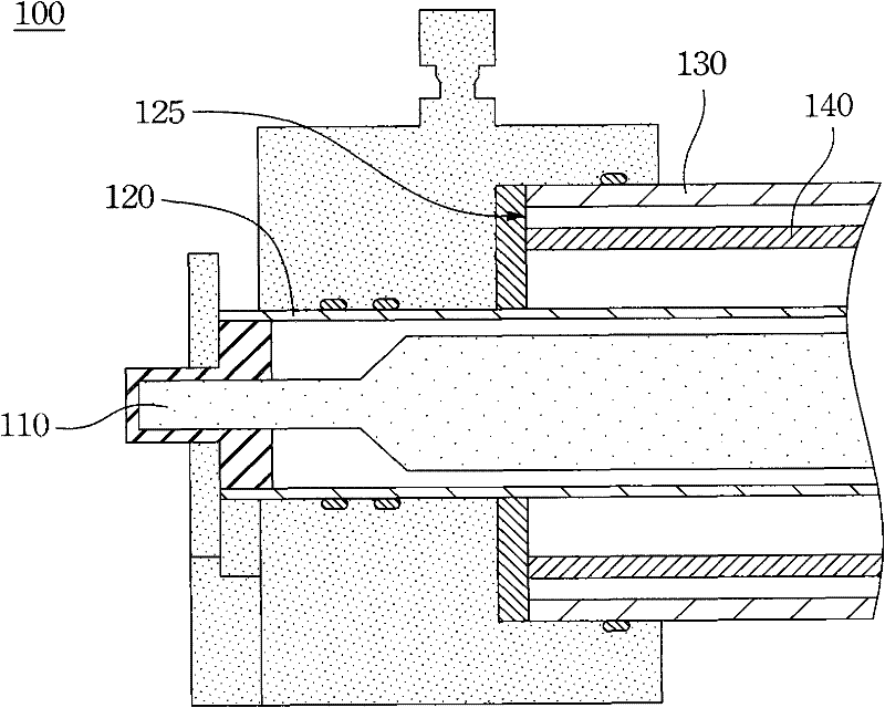
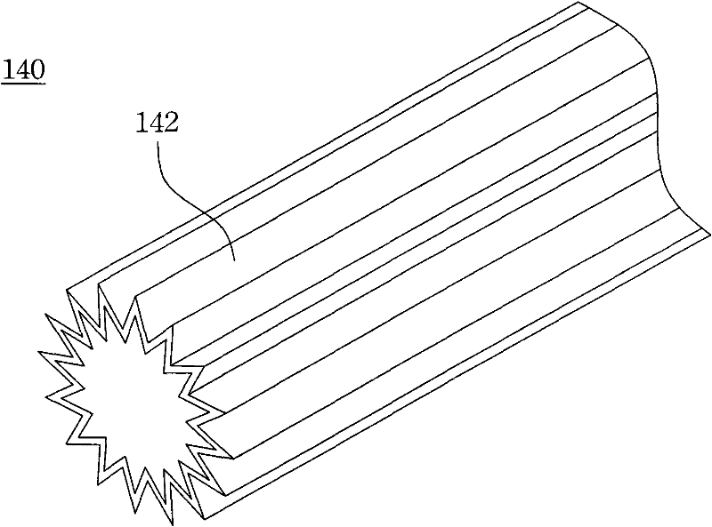
[0039] figure 1 It is a front view of the exposure lamp group 100 according to an embodiment of the present invention. figure 2 for figure 1 Sectional view of part 2 of . As shown in the figure, an exposure lamp set 100 includes a tubular light source 110 , an inner water jacket 120 , an outer water jacket 130 and a tubular filter 140 . The inner water jacket 120 is sleeved on the outside of the tu...


PUM


Abstract

The invention discloses an exposure lighting set and an exposure machine. The exposure lighting set comprises a tube-shaped light source, an inner water jacket, an outer water jacket and a tube-shaped light filter. The inner water jacket sleeves the tube-shaped light source. The outer water jacket sleeves the inner water jacket, thereby a space is formed between the inner and the outer water jackets. The tube-shaped light filter is disposed between the inner and the outer water jackets. The circumferential wall surface area of the tube-shaped light filter is larger than the product of the external diameter circumference and the external diameter length of the tube-shaped light filter. The invention has advantages of providing sufficient heat exchange area; facilitating the cooling system to quickly take away the heat of the tube-shaped light filter.

Description

technical field [0001] The present invention relates to an exposure machine, and in particular to an exposure lamp group. Background technique [0002] The existing ultraviolet exposure lamp group is generally composed of a lamp tube, an inner water jacket, an outer water jacket, and a circular tubular infrared cut-off filter (IR filter). When in use, the light emitted by the lamp will pass through the infrared cut filter, and the infrared cut filter will reflect or absorb the part of the infrared band in the light, so as to prevent the light in the infrared band from affecting the subsequent process, for example: causing unnecessary The temperature rises. [0003] Since the IR cut filter will reflect or absorb part of the infrared band of light, the temperature of the IR cut filter will increase significantly during use. Especially for high-power lamps, this temperature increase is even more pronounced. In order to avoid the high temperature from affecting the life of th...

Claims


Application Information

Patent Timeline
Patent Type & Authority Patents(China)
IPC IPC(8): G03B27/54G02B5/20G03F7/20
Inventor 黄彦杰周上杰许咏政
Owner AU OPTRONICS CORP
Learn More