Programmable logic controller, program compiler, compiling system and method
A technology of programming logic and controller, applied in the direction of program control, memory system, program control design, etc. in sequential/logic controllers, it can solve the problems of low efficiency and long time consumption, and achieve the goal of improving processing efficiency and saving processing time. Effect
Active Publication Date: 2011-06-15
深圳市合信自动化技术有限公司
View PDF5 Cites 22 Cited by
- Summary
- Abstract
- Description
- Claims
- Application Information
AI Technical Summary
Problems solved by technology
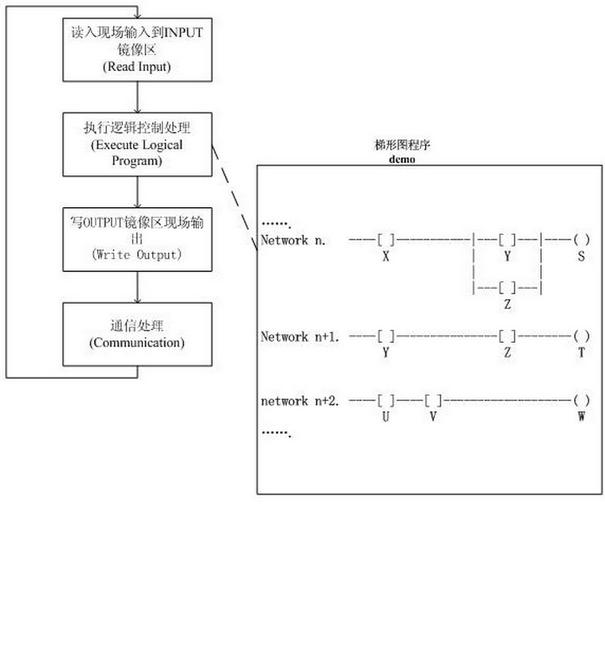
Since the current PLCs are all single-core processors, it takes a long time and low efficiency to execute the above programming languages.
Method used
View moreImage
Smart ImageViewing Examples
Examples
Embodiment Construction
Login to View More PUM
 Abstract
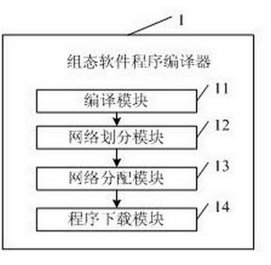
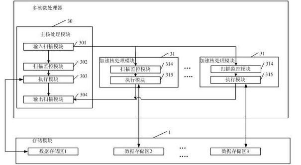
The embodiment of the invention discloses a programmable logic controller, a configuration software program compiler, a compiling system and a compiling method. The programmable logic controller comprises a multi-core microprocessor and a storage module, wherein the multi-core microprocessor further comprises a main core processing module and at least one acceleration core processing module; the main core processing module is used for executing program network segments distributed to the main core processing module; the program network segments are formed by segmenting a compiling program required to be run by the programmable logic controller by using the configuration software program compiler which is connected with the programmable logic controller; and the acceleration core processing module is used for executing program network segments distributed to the acceleration core processing module; and the storage module is used for storing program network segments distributed to the main core processing module and at least one acceleration core processing module respectively through a plurality of data partitions. Through the programmable logic controller, the configuration software program compiler, the compiling system and the compiling method, programming languages compiled on the programmable logic controller can be executed in parallel.
Description
Programmable logic controller, program compiler, compiling system and method technical field The invention relates to the field of programmable logic controllers, in particular to a programmable logic controller, a program compiler, a compiling system and a method. Background technique Programmable logic controller (ProgrammableLogicController, PLC), is a digital logic controller for automatic real-time control, widely used in the current industrial control field. Before the emergence of programmable logic controllers, it is generally necessary to use hundreds of relays and counters to form an automation system with the same function, but now, programmed simple programmable logic controller modules have basically replaced these large device. The system program of the programmable logic controller is generally initialized before leaving the factory, and the user can edit the corresponding user program according to his own needs to meet the different automatic production re...
Claims
Login to View More Application Information
Patent Timeline
 Patent Type & Authority Applications(China)
IPC IPC(8): G05B19/05G06F9/45G06F9/50
Inventor 戎思吉
Owner 深圳市合信自动化技术有限公司
Features
- R&D
- Intellectual Property
- Life Sciences
- Materials
- Tech Scout
- Unparalleled Data Quality
- Higher Quality Content
- 60% Fewer Hallucinations
Learn More Browse by: Latest US Patents, China's latest patents, Technical Efficacy Thesaurus, Application Domain, Technology Topic, Popular Technical Reports.
© 2025 PatSnap. All rights reserved.Legal|Privacy policy|Modern Slavery Act Transparency Statement|Sitemap|About US| Contact US: help@patsnap.com


