Structure for fixing magnetic poles of permanent magnet motor

A technology of fixed magnetic pole and permanent magnet motor, applied in the shape/style/structure of the magnetic circuit, rotating parts of the magnetic circuit, etc., can solve the problem of unreliable positioning of the magnetic pole of the rotor, and achieve easy implementation, accurate installation and positioning accuracy, and reduced The effect of installation difficulty

Active Publication Date: 2011-06-15
HARBIN INST OF TECH
View PDF4 Cites 9 Cited by
  • Summary
  • Abstract
  • Description
  • Claims
  • Application Information

AI Technical Summary

Problems solved by technology

[0006] The purpose of the present invention is to solve the problem of unreliable positioning of the rotor magnetic poles of the inner rotor permanent magnet synchronous motor, and to provide a permanent magnet motor magnetic pole fixing structure

Method used


Image

  • Structure for fixing magnetic poles of permanent magnet motor
  • Structure for fixing magnetic poles of permanent magnet motor
  • Structure for fixing magnetic poles of permanent magnet motor

Examples


specific Embodiment approach 1

[0029] Specific implementation mode one: the following combination Figure 1 to Figure 6 To describe this embodiment,

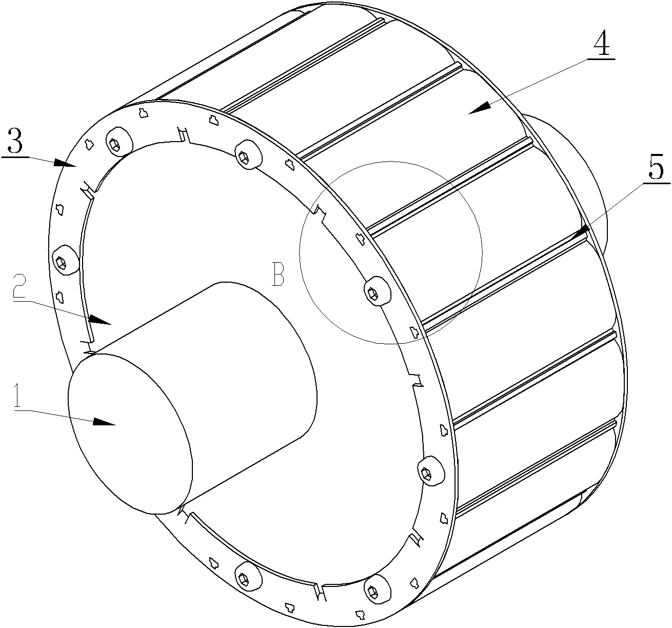
[0030] This embodiment includes a rotating shaft 1 and a rotor yoke 2. The rotor yoke 2 is sleeved on the outer surface of the rotating shaft 1. It also includes two annular rotor pressure plates 3, P magnetic poles 4 and P positioning keys 5.

[0031] Two ring-shaped rotor pressure plates 3 are respectively fixedly connected to both ends of the rotor yoke 2, and form grooves with the outer surface of the rotor yoke 2. P positioning keys 5 are evenly distributed along the circumferential direction of the rotor, and the grooves are evenly divided. There are P accommodating spaces along the axial direction of the rotor, and one magnetic pole 4 is fixedly arranged in each accommodating space.

specific Embodiment approach 2

[0032] Specific implementation mode two: the following combination Figure 1 to Figure 9 Describe this embodiment, this embodiment is a further description of Embodiment 1,

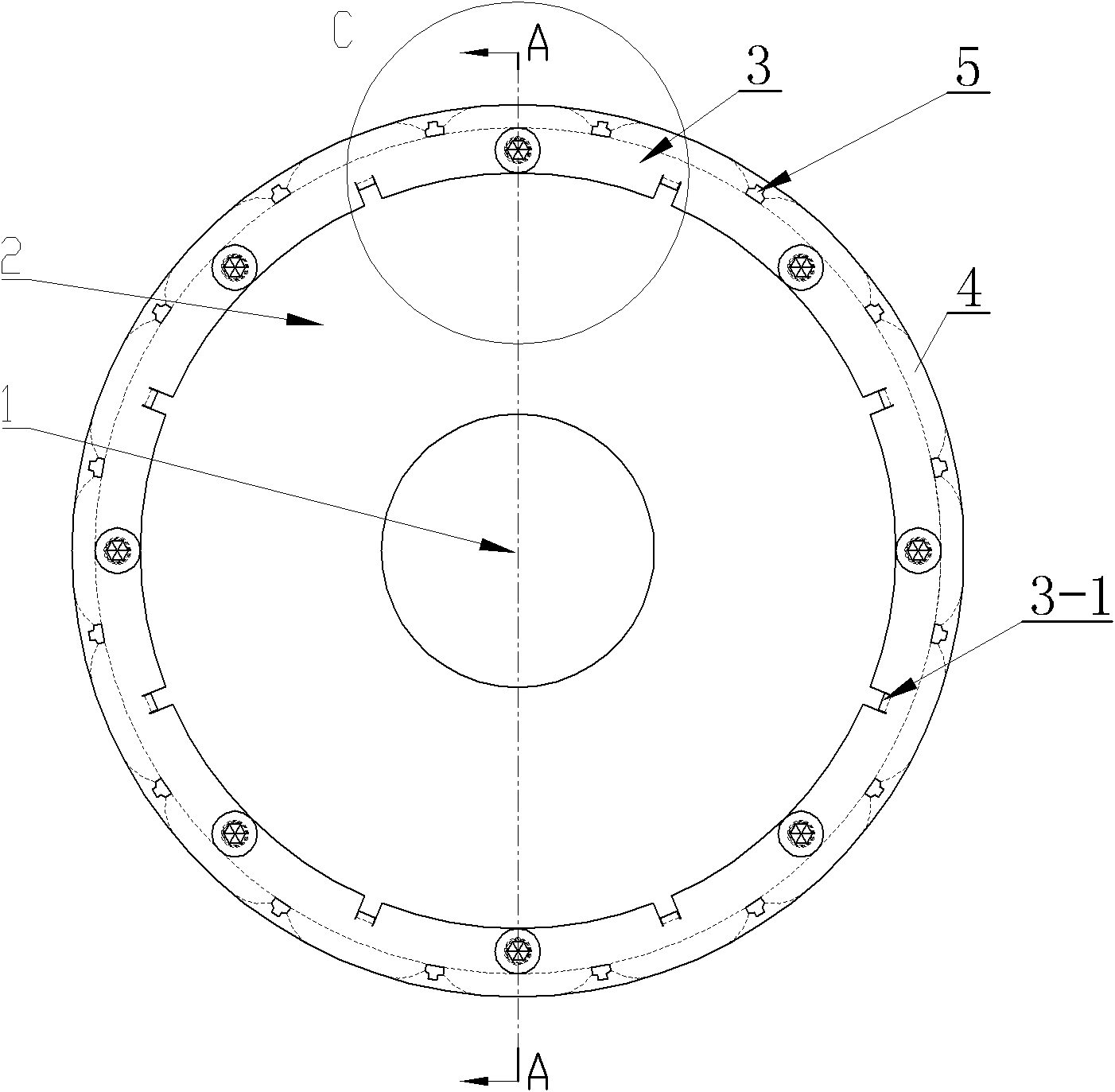
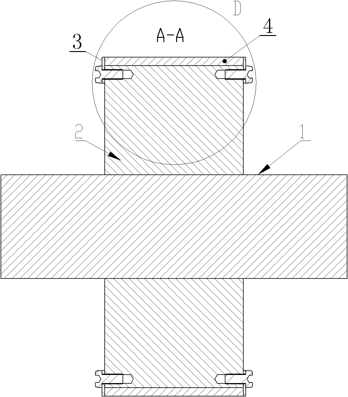
[0033] A plurality of positioning pins 3-1 are stamped on each annular rotor pressure plate 3, and a positioning hole 2-1 is provided on the rotor yoke 2 corresponding to each positioning pin 3-1. The positioning pin 3-1 is tenon-jointed with the positioning hole 2-1 one by one; each annular rotor pressure plate 3 is fixedly connected with the rotor yoke 2 through a plurality of screws, and the plurality of screws are evenly distributed on the annular rotor pressure plate 3 , and spaced apart from the positioning pin 3-1.

[0034] Others are the same as the first embodiment.

[0035] In this embodiment, a plurality of positioning pins 3 - 1 are respectively embedded in a plurality of positioning holes 2 - 1 to realize the positioning of the annular rotor pressure plate 3 in the circumferential direction...

specific Embodiment approach 3

[0036] Specific implementation mode three: the following combination Figure 1 to Figure 9 Describe this embodiment, this embodiment is a further description of Embodiment 1 or 2,

[0037] P slots 3-2 are uniformly arranged on each annular rotor pressure plate 3, and each slot 3-2 is used to fix one end of a positioning key 5.

[0038] Others are the same as the first or second embodiment.


PUM


Abstract

The invention provides a structure for fixing the magnetic poles of a permanent magnet motor, belonging to the technical field of motors and solving the problem that the magnetic poles of the rotors of the inner rotor permanent magnet synchronous motors are positioned unstably. The structure comprises a rotating shaft and a rotor yoke, wherein the rotor yoke is sleeved on the excircle surface of the rotating shaft. The structure also comprises two circular ring-shaped rotor pressing plates, P-numbered magnetic poles and P-numbered positioning keys, wherein the two circular ring-shaped rotor pressing plates are respectively connected at the two ends of the rotor yoke fixedly and form grooves with the outer surface of the rotor yoke; the P-numbered positioning keys are uniformly distributed along the circumferential direction of the rotor and divide the grooves into P-numbered accommodating space along the axial direction of the rotor; and one magnetic pole is fixedly arranged in each accommodating space. The structure is suitable for positioning the magnetic poles of the inner rotor permanent magnet motors.

Description

technical field [0001] The invention relates to a magnetic pole fixing structure of a permanent magnet motor, which belongs to the technical field of motors. Background technique [0002] The permanent magnet synchronous motor and its servo system are widely used in the fields of industrial drive and servo control because of its small size, high efficiency and good dynamic response characteristics. From the perspective of motor structure, permanent magnet synchronous motors can be divided into two types: inner rotor structure and outer rotor structure. Compared with the outer rotor structure, the permanent magnet synchronous motor with the inner rotor structure has the following advantages: [0003] The winding and stator core of the inner rotor motor are installed on the outside of the rotor, so the heat dissipation surface area of ​​the motor is relatively large, and the thermal performance of the motor is better; the moment of inertia of the inner rotor motor is relative...

Claims


Application Information

Patent Timeline
Patent Type & Authority Applications(China)
IPC IPC(8): H02K1/28
Inventor 邹继斌江善林徐永向胡建辉
Owner HARBIN INST OF TECH
Why Eureka
Try Eureka