
Doherty amplifier

A technology for amplifiers and detectors, applied to amplifiers, improved amplifiers to improve efficiency, parts of amplifiers, etc., can solve the problems of Doherty amplifiers not showing performance, achieve compact cost, increase power capacity, and improve efficiency and the effect of linearity

Active Publication Date: 2011-06-15
AMPLEON NETHERLANDS
View PDF9 Cites 10 Cited by
  • Summary
  • Abstract
  • Description
  • Claims
  • Application Information

AI Technical Summary

Problems solved by technology

[0008] However, it has been found that a Doherty amplifier may not exhibit sufficient performance, especially with regard to its gain, linearity and / or efficiency

Method used


Image

  • Doherty amplifier
  • Doherty amplifier
  • Doherty amplifier

Examples


Embodiment Construction

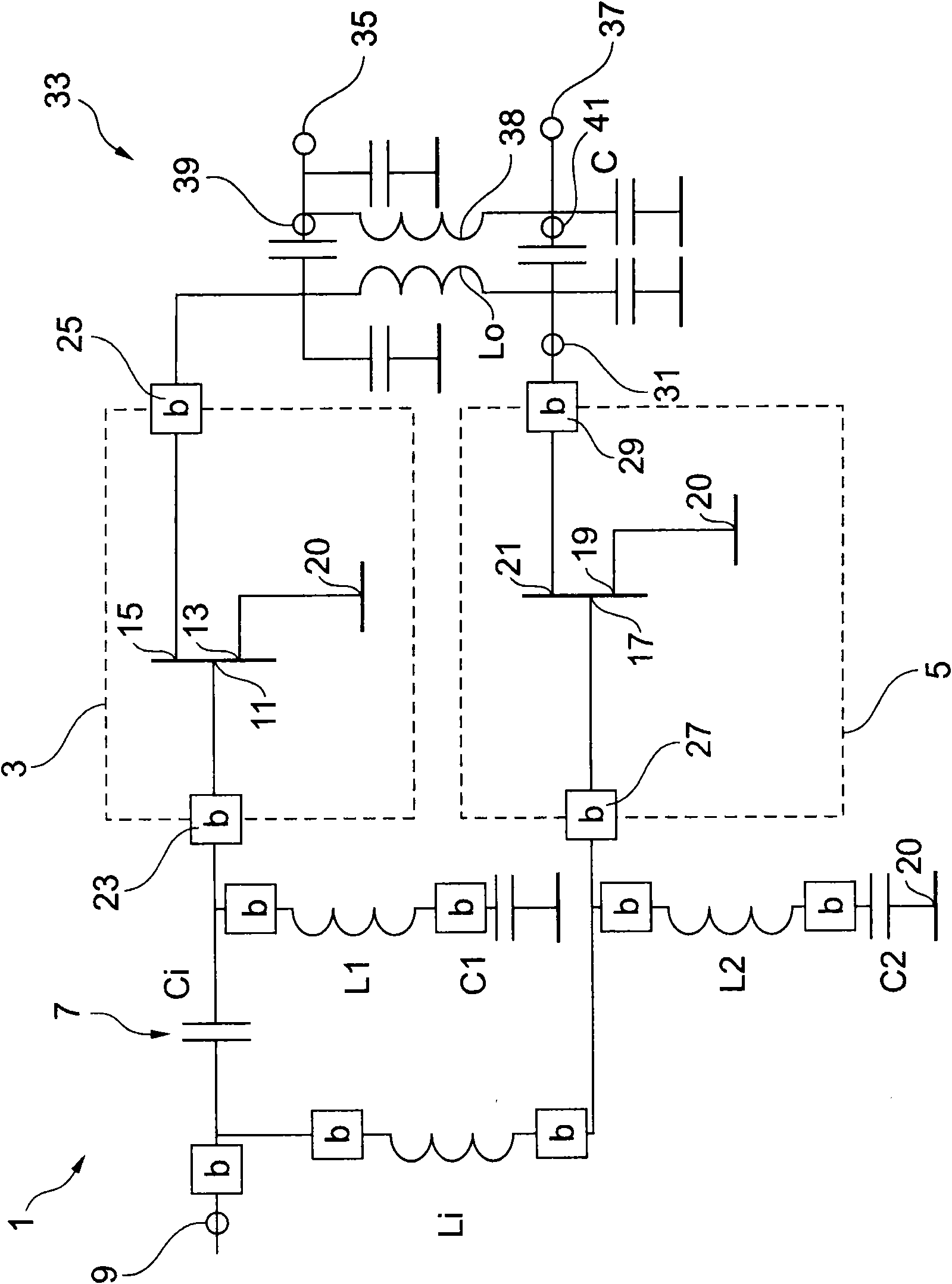
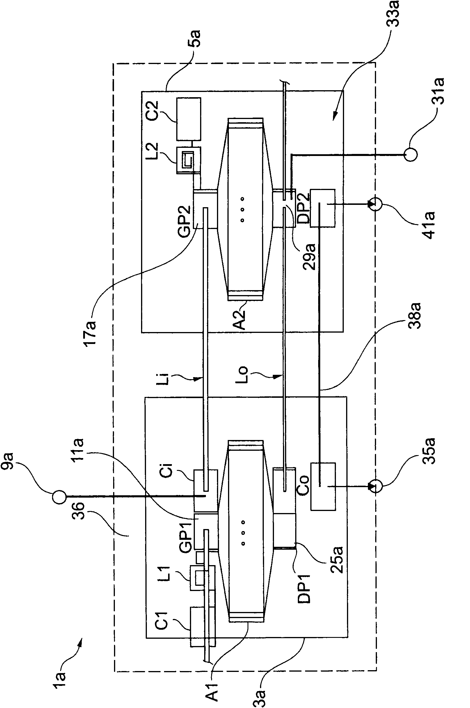
[0036] figure 1 A circuit diagram of a Doherty amplifier 1 according to an embodiment is shown. The Doherty amplifier 1 includes a main amplifier 3 and a peak amplifier 5, both of which are field effect transistors (FETs). The Doherty amplifier 1 also comprises an input part 7 comprising inductors Li, L1, L2 and capacitors Ci, C1 and C2. In addition, the Doherty amplifier 1 includes a Doherty amplifier input terminal 9 in the input section 7 to which an input signal such as an RF signal (for example, an amplitude-modulated signal of a carrier with a frequency up to several GHz) can be applied. Amplifier input terminal 9 is amplified by Doherty amplifier 1 .

[0037] The main amplifier 3 , represented as a FET, comprises a gate terminal 11 , a source terminal 13 and a drain terminal 15 . The source terminal 13 is grounded, ie ground potential 20 . The main amplifier 3 includes a main input terminal 23 and a main output terminal 25 .

[0038] The peaking amplifier 5 represe...


PUM


Abstract

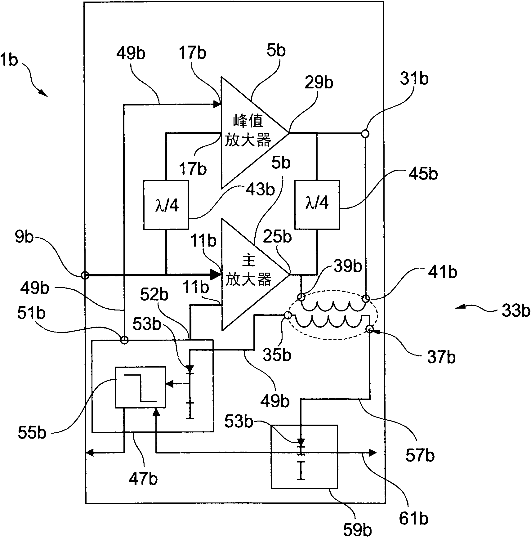
A combination amplifier, in particular a Doherty amplifier allowing dynamic biasing, is provided, the combination amplifier comprising a first amplifier (3,3a,3b) having a first input terminal (11,11a,11b) and a first output terminal (25,25a,25b); a second amplifier (5,5a,5b) having a second input terminal (27,27a,27b) and a second output terminal (29,29a,29b); a first impedance inverter (Li, 43b) connected between the first input terminal and the second input terminal; and an envelope detector (33,33a,33b) comprising a detector output terminal and a detector input terminal which is connected to the first output terminal.

Description

technical field [0001] This invention relates to combined amplifiers, and more particularly to Doherty amplifiers. Still more particularly, the invention relates to a Doherty amplifier comprising an envelope detector. More specifically, the present invention relates to Doherty amplifiers allowing dynamic bias control. Background technique [0002] In communication technologies such as wireless communication technologies, very high power RF amplifiers are required to transmit modulated RF signals having time-variable amplitudes and characterized by the ratio of peak power to average power level (PAR). The RF amplifier used not only needs to output high power, but also needs to be able to efficiently amplify the RF signal in a linear fashion at the average power level. Different types of transistors can be used for amplification. Also, transistors can work in different classes. The operational class (A class, AB class, B class and C class) of the transistor or amplifier in...

Claims


Application Information

Patent Timeline
IPC IPC(8): H03F1/07
CPCH03F1/0288
Inventor 伊戈尔·布莱德诺夫
Owner AMPLEON NETHERLANDS
Learn More