Interface logic for a multi-core system-on-a-chip (SOC)

A technology of interface logic and logic, applied in the field of interface logic

Active Publication Date: 2011-06-22
INTEL CORP
View PDF4 Cites 10 Cited by
  • Summary
  • Abstract
  • Description
  • Claims
  • Application Information

AI Technical Summary

Problems solved by technology

Typically, SoCs include single-core processors, which can place limits on their usefulness

Method used


Image

  • Interface logic for a multi-core system-on-a-chip (SOC)
  • Interface logic for a multi-core system-on-a-chip (SOC)
  • Interface logic for a multi-core system-on-a-chip (SOC)

Examples


Embodiment Construction

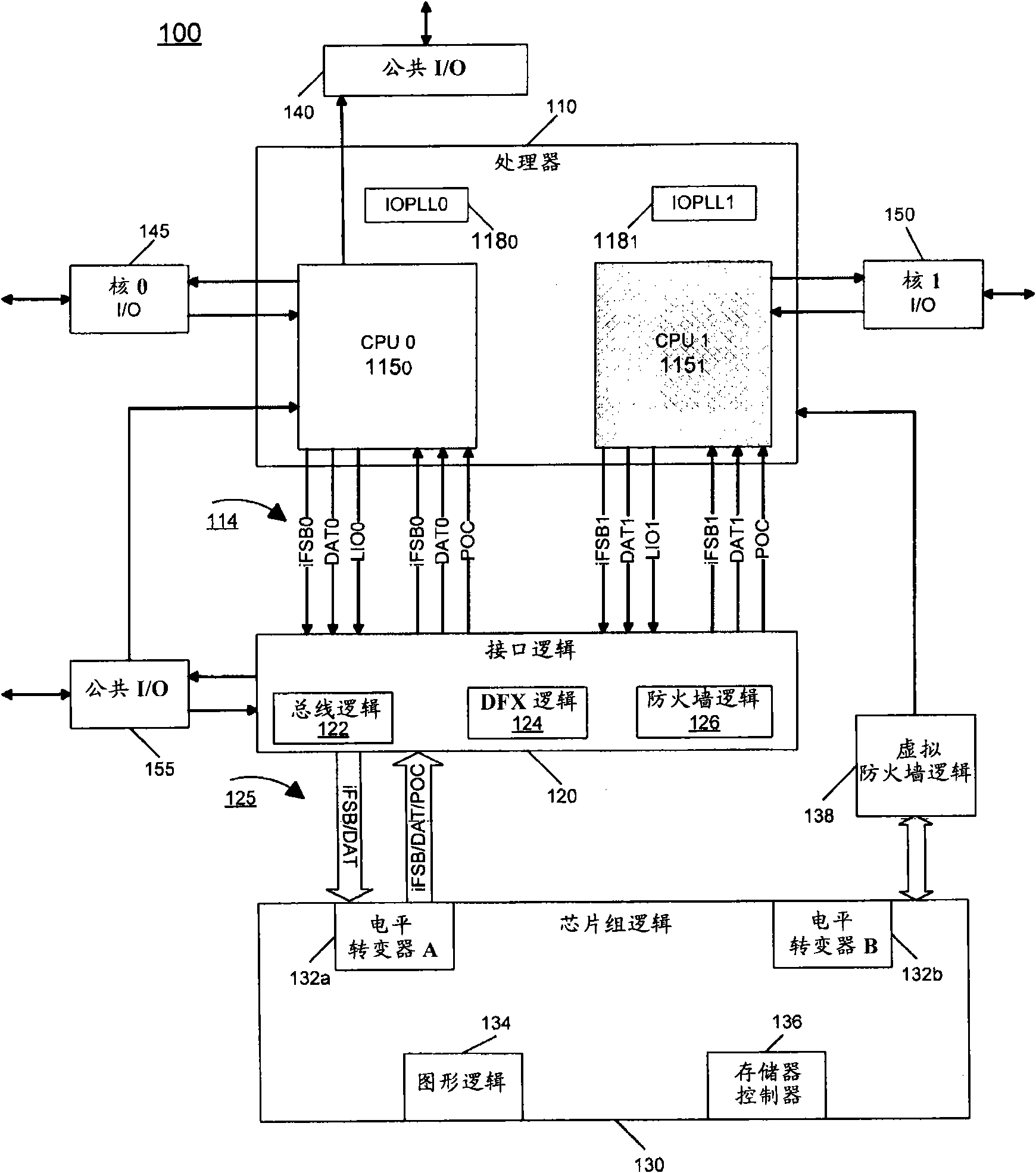
[0012] In various embodiments, a multi-core system-on-chip (SoC) may be provided with interface logic to one or more integrated cores (also referred to herein as a central processing unit (CPU)), as well as with an integrated memory controller and Associated input / output (10) buffers. The CPU, which may be a pair of cores in one embodiment, is coupled to the rest of the SoC via an internal front side bus (FSB) interconnect. The interface logic also provides functional and test access for configurations as single core (in addition to dual core) for market and high volume manufacturing (HVM) flexibility. In one embodiment, the interface logic component can interface the two CPUs with other chipset logic in the SoC (eg, Northbridge controller). Interface logic can be fused (fuse) to support single-core or dual-core product base keeping unit (product stock keeping unit) (SKU).

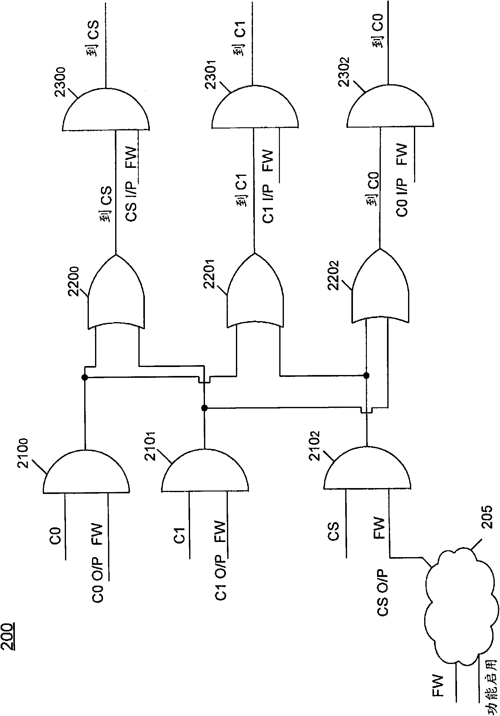
[0013] In one embodiment, the interface logic can thus be used to resolve the dual-core CPU iFSB (Int...


PUM


Abstract

In one embodiment, the present invention includes a system-on-a-chip (SoC) with first and second cores, interface logic coupled to the cores, chipset logic coupled to the interface logic, and a virtual firewall logic coupled between the chipset logic and the second core. The interface logic may include a firewall logic, a bus logic, and a test logic, and the chipset logic may include a memory controller to provide for communication with a memory coupled to the SoC. In some system implementations, both during test operations and functional operations, the second core can be disabled during normal operation to provide for a single core SoC, enabling greater flexibility of use of the SoC in many different implementations. Other embodiments are described and claimed.

Description

technical field [0001] The present invention relates to interface logic for a multi-core system-on-chip (SOC). Background technique [0002] As semiconductor technology evolves, a greater number of functional properties are combined on a single semiconductor die. While separate integrated circuits may have previously existed to provide different functions such as processing functions, control functions, interface functions, etc., modern semiconductors are able to combine multiple functions such as these functions in a single integrated circuit. [0003] Evidence of this trend is the continuously increasing number of available system-on-chip (SoC) devices. These single-die integrated circuits (ICs) include various circuits such as processing circuits, interface circuits, application specific function circuits, and the like. Therefore, portable devices such as mobile terminals, netbooks, and the like and embedded devices can be realized with a smaller number of devices. Thi...

Claims


Application Information

Patent Timeline
Patent Type & Authority Applications(China)
IPC IPC(8): G06F15/80
CPCY02B60/1225G01R31/318572G06F15/7842G06F15/7807G06F13/40Y02D10/00
Inventor R·拉查康达L·E·哈金M·K·雷迪L·R·博尔格C·H·戴P·P·巴蒂亚J·P·李
Owner INTEL CORP
Why Eureka
Try Eureka