
Method for judging input overflowing amplitude of pipelining type analog-to-digital converter

A technology for analog-to-digital converters and judging pipelines, applied in the direction of analog-to-digital converters, etc., can solve the problems of system efficiency reduction, unknown overflow range, and unpredictable adjustment process time, so as to improve efficiency and shorten adjustment time Effect

Active Publication Date: 2011-06-22
杭州思泰微电子有限公司
View PDF4 Cites 3 Cited by
  • Summary
  • Abstract
  • Description
  • Claims
  • Application Information

AI Technical Summary

Problems solved by technology

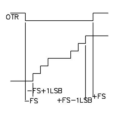
When the signal input to the analog-to-digital converter is not within its range, the general data converter will output an overflow flag signal (OTR), and clamp the output to all 0 or all 1, see figure 1 , it can be seen from the figure that when the analog input signal exceeds the input range of the analog-to-digital converter, the subsequent digital processing circuit can only know whether the analog input signal is positive overflow or negative overflow through the OTR and the output signal of the analog-to-digital converter. The digital processor repeats the process of "reducing the gain of the adjustable amplifier - detecting whether the data converter overflows" until the data converter does not overflow. Since the overflow magnitude of the data converter input is unknown, it is impossible to predict the time required for the entire adjustment process, making reduced system efficiency

Method used


Image

  • Method for judging input overflowing amplitude of pipelining type analog-to-digital converter
  • Method for judging input overflowing amplitude of pipelining type analog-to-digital converter
  • Method for judging input overflowing amplitude of pipelining type analog-to-digital converter

Examples


specific Embodiment 1

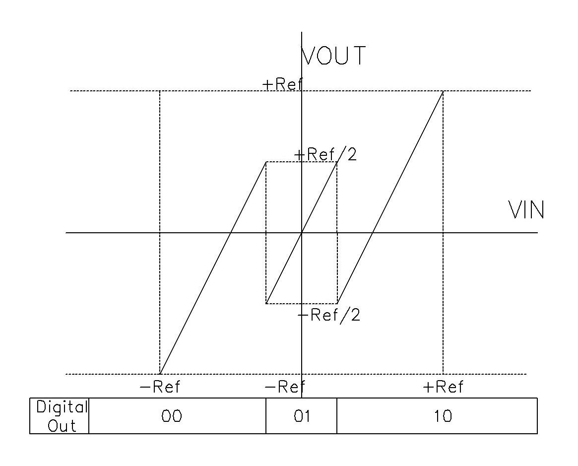
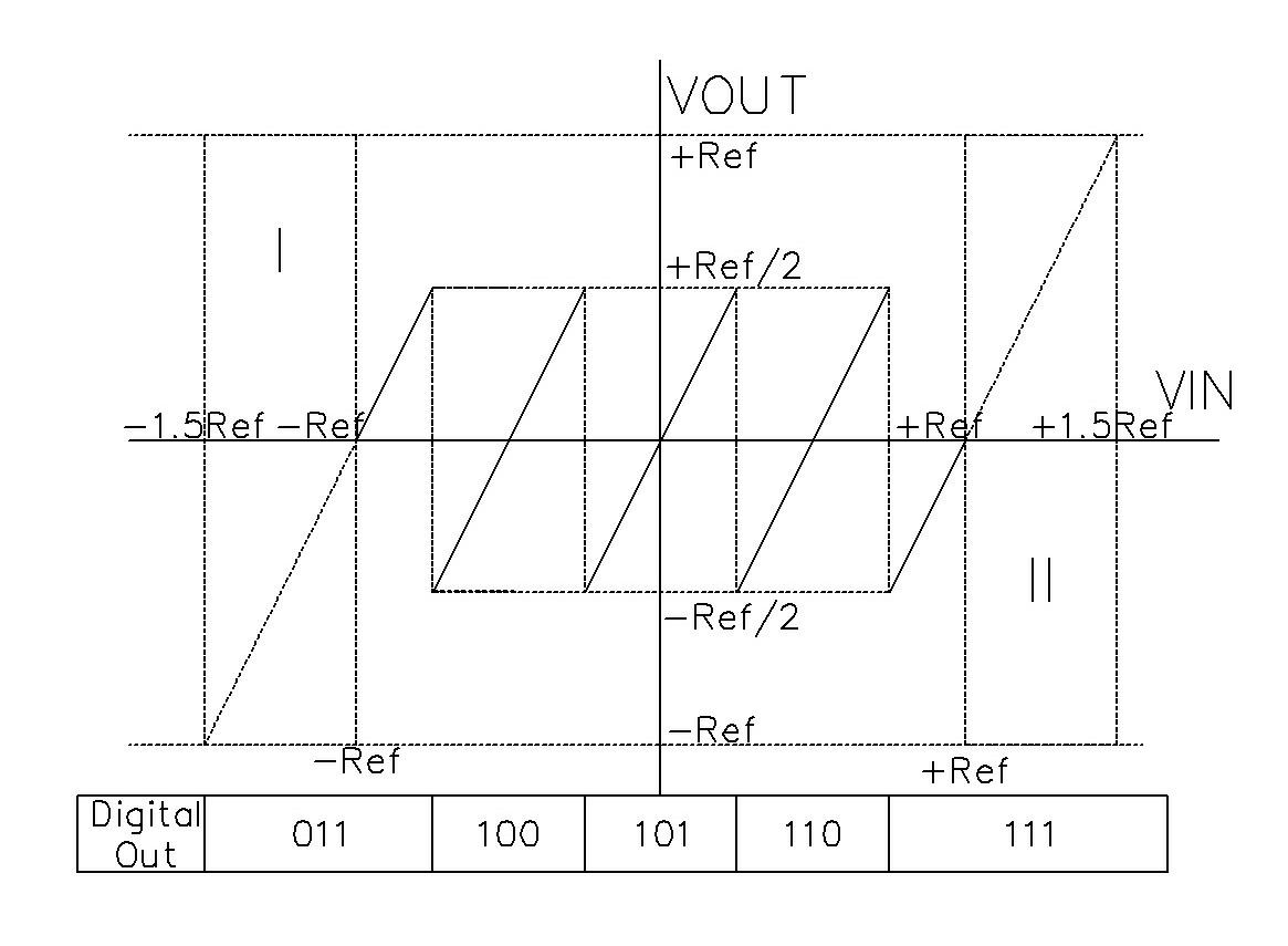
[0020] Specific embodiment one: the first stage adopts the judging method of the input overflow range of ten pipelined analog-to-digital converters of 1.5bit, see image 3 , Figure 5 , Figure 6 , after the signal is input into the pipeline analog-to-digital converter, the digital circuit of the first stage adopts a three-digit digital encoding method, and the outputs of the other nine digital circuits are all traditional digital encoding methods. The last bit is added, the digital output after the addition is completed, and the first digit of the first-level digital output does not participate in the addition process, which is the internal overflow judgment bit; when the addition is completed, the first two digits of the digital output are set to 11, internal When the overflow judgment bit is 0, and the highest bit corresponding to the output of the remaining nine stages except the first stage is 0, it is judged to be a negative overflow, and the overflow flag bit signal is...

specific Embodiment 2

[0021] Specific embodiment two: the first stage adopts the judging method of the input overflow range of ten pipelined analog-to-digital converters of 1.5bit, see Figure 4 , Figure 5 , Figure 7 , after the signal is input into the pipeline analog-to-digital converter, the digital circuit of the first stage adopts a three-digit digital encoding method, and the outputs of the other nine digital circuits are all traditional digital encoding methods. The last bit is added, the digital output after the addition is completed, and the first digit of the first-level digital output does not participate in the addition process, which is the internal overflow judgment bit; when the addition is completed, the first two digits of the digital output are set to 11, internal When the overflow judgment bit is 1, and the highest bit corresponding to the output of the remaining nine stages except the first stage is 0, it is judged to be a negative overflow, and the overflow flag bit signal i...

specific Embodiment 3

[0022]Specific embodiment three: the first stage adopts the judging method of the input overflow range of the eight-bit pipelined analog-to-digital converter of 1.5bit, see Figure 4 , Figure 5 , Figure 8 , after the signal is input into the pipeline analog-to-digital converter, the first-stage digital circuit adopts a three-digit digital encoding method, and the outputs of the remaining seven-stage digital circuits are all traditional digital encoding methods. The last bit is added, the digital output after the addition is completed, and the first bit of the first-level digital output does not participate in the addition process, and is an internal overflow judgment bit;

[0023] It is set that when the first two digits of the digital output are 11 after the addition is completed, the internal overflow judgment bit is 1, and the corresponding highest bit of the remaining seven outputs except the first level is 0 after the addition, it is judged to be negative Overflow, th...


PUM


Abstract

The invention relates to a method for judging the input overflowing amplitude of a pipelining type analog-to-digital converter, which has the advantages of shortening adjusting time and improving efficiency. A pipelining type analog-to-digital converter of 1.5 bit is adopted in a first level. The method is characterized by comprising the steps of: inputting a signal into the pipelining type analog-to-digital converter, enabling a first-level digital circuit to adopt a 3-bit digital encoding mode and enabling other digital circuits to output in a traditional digital encoding mode; adding the initial bit of the later level and the last bit of the former level to finish the output of added digits, wherein the output initial bit of the first-level digit does not participate in an addition process and is an internal overflowing judging bit; judging on negative overflowing or positive overflowing when digit output after programming settings are added, the internal overflowing judging bit, and the corresponding highest bit of the sum of the output rest levels except the first level meet corresponding conditions; and then, setting an overflowing flag signal to be 1, fully negating the data subjected to output of the added digits to acquire final digit output, i.e. to acquire accurate amplitude in a measuring range within 0.5 time.

Description

technical field [0001] The invention relates to the field of pipeline analog-to-digital converters, in particular to a method for judging the input overflow range of pipeline-type analog-to-digital converters. Background technique [0002] Due to its balanced performance in speed, power consumption, performance, area, etc., pipelined analog-to-digital converters have achieved rapid development in recent years and are widely used in medium and large systems such as video, medical, communication, industry, and national defense. , At present, the accuracy of the pipelined analog-to-digital converter covers 8~14 bits, and the speed covers from 10MHz to 250MHz. In an SOC or board-level system with a pipelined digital-to-analog converter, in order to adapt to the large input range of external natural signals, a gain-adjustable amplifier is added before the analog-to-digital converter, and the subsequent digital processing of the analog-to-digital converter The controller automati...

Claims


Application Information

Patent Timeline
Patent Type & Authority Applications(China)
IPC IPC(8): H03M1/12
Inventor 应祖金吴明远
Owner 杭州思泰微电子有限公司
Learn More