
Frame of computer flat knitting machine

A flat knitting machine and knitting technology, which is applied in knitting, weft knitting, textiles and papermaking, etc. It can solve the problems that it is difficult to ensure the structural size consistency of the frame, the size error of the frame is difficult to control, and it is not suitable for mass production. , to achieve the effect of favorable packaging, firm and stable weight, and light weight

Inactive Publication Date: 2011-06-29
JIANGSU JINLONG TECHNOLOGY CO LTD
View PDF2 Cites 4 Cited by
  • Summary
  • Abstract
  • Description
  • Claims
  • Application Information

AI Technical Summary

Problems solved by technology

Although this patented technical solution can eliminate many deficiencies of the frame of the cast structure, there are still problems of cumbersome manufacture, for example, the upper flat steel plate and the second flat steel plate need to be welded through a pair of elbows, and the second flat steel plate needs to be welded with the lower flat steel plate. Steel plate welding, etc., so the consumption of auxiliary materials such as solder for processing this kind of rack is large, the process links are many, the workload of workers is heavy, it is not suitable for mass production, and it is difficult to ensure the consistency of the structural size of the rack , the frame size error (tolerance) of each batch is difficult to control, leaving installation difficulty for the computerized flat knitting machine

Method used


Image

  • Frame of computer flat knitting machine
  • Frame of computer flat knitting machine

Examples


Embodiment Construction

[0018] In order to enable the examiners of the patent office, especially the public, to understand the technical essence and beneficial effects of the present invention more clearly, the applicant will describe in detail below in conjunction with the accompanying drawings in the form of embodiments, but none of the descriptions of the embodiments is a description of the present invention. Restriction of the inventive solution, any equivalent transformation made according to the concept of the present invention which is only in form but not in substance shall be regarded as the scope of the technical solution of the present invention.

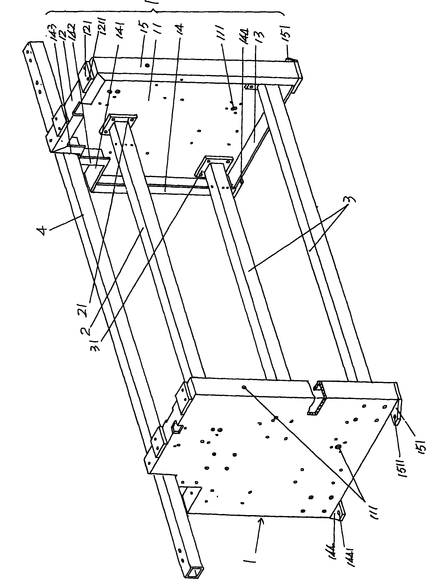
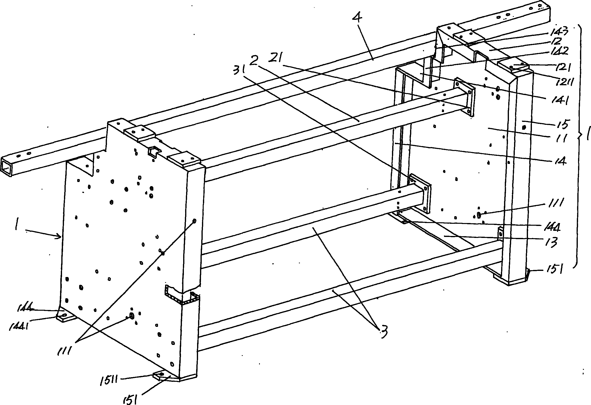
[0019] Please refer to the accompanying drawings, a pair of wallboards 1 opposite to the left and right are shown in the accompanying drawings, because the shape and size of a pair of wallboards 1 and the specific structure are exactly the same, so the applicant only aims at the following A wallboard 1 is described in detail. Wallboard 1 compris...


PUM


Abstract

The invention provides a frame of a computer flat knitting machine, belonging to the field of knitting machines, comprising a pair of wall plates of same structure and connected by upper and lower beams, wherein each wall plate comprises a plate body, a top folded edge, a bottom folded edge, a left folded edge and a right folded edge, the top folded edge, the bottom folded edge, the left folded edge and the right folded edge are bent in the same direction to form the edge of the plate body, one end of the upper folded edge is connected with the upper end of the left folded edge, the other end of the upper folded edge is connected with the upper end of the right folded edge, one end of the lower folded edge is connected with the lower end of the left folded edge, and the other end of the lower folded edge is connected with the lower end of the right folded edge. The frame can be rapidly manufactured, and raw materials are saved; the wall plates are light and firm so as to save material and be beneficial to packaging and reducing the transportation cost; and the structure of each wall plate can be obtained without welding, so as to reduce the labor strength of workers.

Description

technical field [0001] The invention belongs to the technical field of knitting machinery, and in particular relates to a frame of a computerized flat knitting machine. Background technique [0002] There are two types of flat knitting machines, one is a manual flat knitting machine, and the other is a computerized flat knitting machine. In view of this, there are also two types of flat knitting machine frames. The frame of the flat knitting machine, and the second is the frame suitable for the computer knitting flat knitting machine. The frame suitable for manual horizontal knitting is as the frame structure frame disclosed by the Chinese Utility Model Authorization Notice No. CN2617793Y. The structure of a flat knitting machine is very different from that of a manual flat knitting machine, because the frame of a computerized flat knitting machine is usually closed and has very strict requirements on sturdiness and stability. [0003] The existing technology often adopts ...

Claims


Application Information

Patent Timeline
Patent Type & Authority Applications(China)
IPC IPC(8): D04B15/00
Inventor 金永良兰先川张和中
Owner JIANGSU JINLONG TECHNOLOGY CO LTD
Learn More