
Inner plugging air bag for leakage of risk source pipeline and quick plugging method thereof

A pipeline leakage and risk source technology, which is applied in the pipeline leakage sealing device and its sealing field, to achieve the effects of speeding up the sealing, easy processing and manufacturing, and simple structure

Inactive Publication Date: 2011-06-29
TAIYUAN UNIV OF TECH
View PDF2 Cites 20 Cited by
  • Summary
  • Abstract
  • Description
  • Claims
  • Application Information

AI Technical Summary

Problems solved by technology

[0005] The present invention provides a leaking internal plugging air bag of a risk source pipeline and a rapid plugging method thereof, so as to solve the problem of fast sealing of the risk source pipeline in an emergency situation in which the risk source pipeline leaks, and realize effective time saving and reduction purpose of loss

Method used


Image

  • Inner plugging air bag for leakage of risk source pipeline and quick plugging method thereof
  • Inner plugging air bag for leakage of risk source pipeline and quick plugging method thereof
  • Inner plugging air bag for leakage of risk source pipeline and quick plugging method thereof

Examples


Embodiment 1

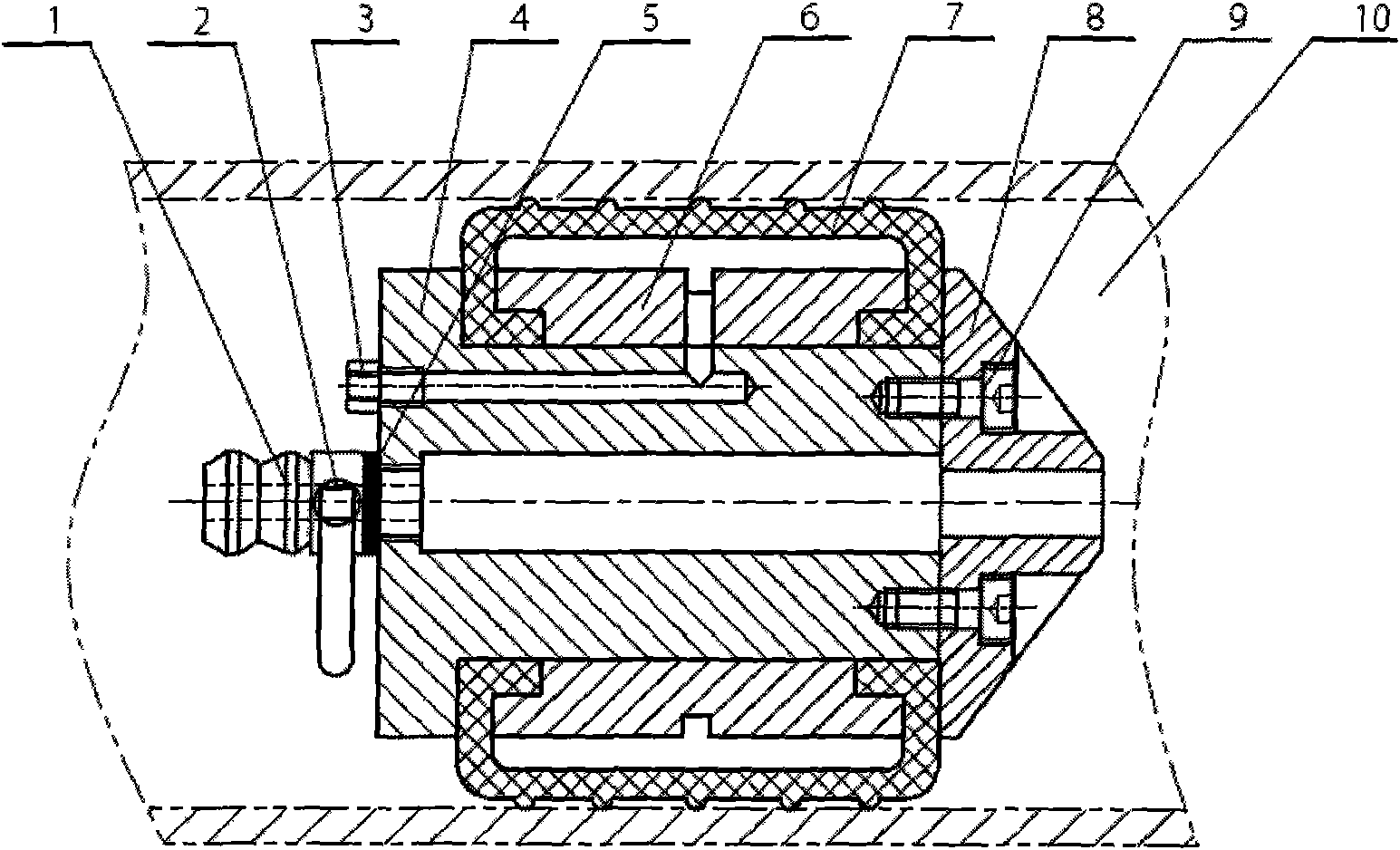
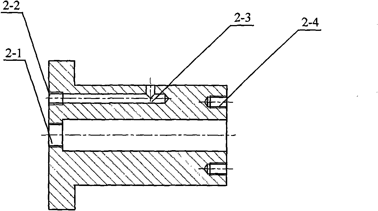
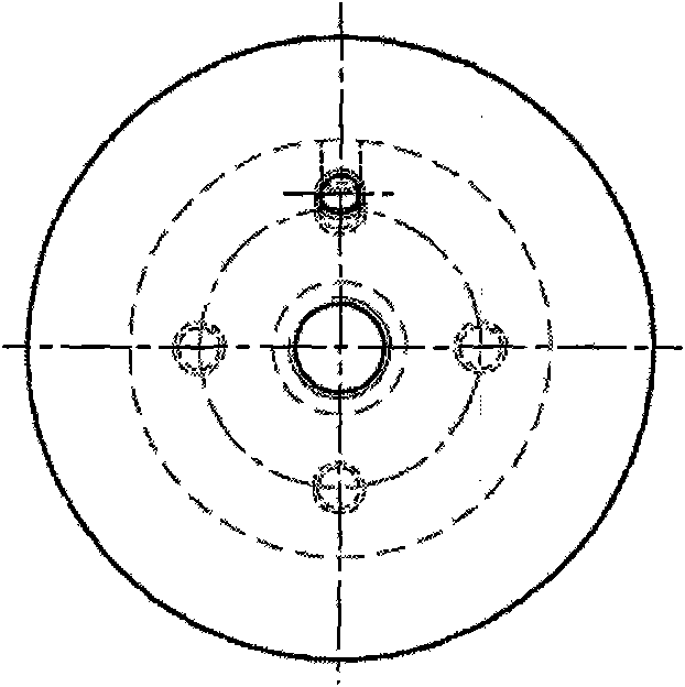
[0028] Such as Figure 1-Figure 9 According to the present invention, a risk source pipeline leakage internal plugging diversion air bag and its plugging method are implemented, and its mechanical structure includes a sealing mechanism, a diversion mechanism, a holding mechanism and a fixing structure.

[0029] Among them, the sealing mechanism includes a blocking air bag 7; the diversion mechanism includes a diversion tube nozzle 1, a diversion ball valve 2, and a sealing gasket 5, wherein the diversion tube nozzle can be externally connected to the diversion tube; the holding mechanism includes a hollow shaft sleeve 4 and its The inflation joint 3 on the left end face; the fixing mechanism includes an air bag compression sleeve 6 and a tapered flange cover 8 .

[0030] Wherein, the connection of the diversion mechanism is through the diversion pipe joint 1 and the diversion ball valve 2 through threaded connection, and then the diversion ball valve thread on the left end sur...

Embodiment 2

[0032] Such as Figure 1-Figure 9 , implementing a kind of risk source pipeline leakage internal plugging diversion air bag and its plugging method of the present invention, the plugging method is that after the sealing mechanism, the diversion mechanism, the holding mechanism and the fixed structure are installed together, at first the diversion Connect the diversion tube on the pipe joint 1, and connect the inflation tube on the inflation joint 3. Install the whole set of internal blocking airbags in the risk source pipeline 10, open the diversion ball valve 2, then inflate into the blocking airbag 7 through the inflation tube, and finally close the diversion ball valve 2, so as to realize the rapid sealing of the risk source pipeline 10. Divert if necessary. Open diversion ball valve 2 with special tool and get final product.

[0033] The pipe internal plugging and diversion airbag can be directly applied to the leakage of the straight mouth of the pipeline. In the case o...


PUM


Abstract

The invention discloses an inner plugging air bag for leakage of a risk source pipeline and a quick plugging method thereof. The plugging device of the risk source pipeline consists of a sealing mechanism, a flow guide mechanism, a retaining mechanism and a fixing mechanism which are connected with one another. In the method, the plugging air bag, an aeration joint external aeration pump, a flow guide pipe connecting nozzle and a flow guide ball valve are used as plugging flow guide elements; and quick plugging for pipeline leakage is realized by aerating the plugging air bag by using extensibility of the rubber air bag. The inner plugging air bag has a simple structure, light weight and a good plugging effect, can be repeatedly used, is suitable for plugging the risk source pipeline of toxic gas and liquid and the like, and can also be used for inner plugging for leakage of a heat pipeline, a water supply pipeline, a chemical industry pipeline and even a large-sized pipeline.

Description

technical field [0001] The invention relates to a pipeline leakage sealing device and a sealing method thereof, in particular to a pipeline leakage sealing air bag used for the risk source of pipeline leakage in the process of petrochemical and coal chemical production and storage and transportation and its rapid sealing It can also be used for emergency plugging of pipelines such as gas, heat and water supply. Background technique [0002] Human beings produce many chemicals to meet the needs of daily life, about 4 billion tons per year. These substances are extremely dangerous in the process of production, storage and transportation. Once an accident occurs, it will cause serious consequences. [0003] The existing pipeline leakage plugging mainly includes injection type plugging under pressure, external sealing type plugging, binding type plugging, cork plugging, metal plugging, injection type plugging and sticking type plugging, injection type The pressure sealing devic...

Claims


Application Information

Patent Timeline
Patent Type & Authority Applications(China)
IPC IPC(8): F16L55/134
Inventor 寇子明卫进高贵军李军霞安宁闫宏伟
Owner TAIYUAN UNIV OF TECH
Learn More